Hip joint femoral stem fatigue test loading device

A fatigue test and loading device technology, applied in the field of medical fatigue experiments, can solve problems such as experimental failure, prosthesis damage, inability to solve lateral stress well, and achieve the effect of ensuring stability

Active Publication Date: 2022-03-01
合肥熠品医药科技有限公司 +2
View PDF8 Cites 0 Cited by
  • Summary
  • Abstract
  • Description
  • Claims
  • Application Information

AI Technical Summary

Problems solved by technology

[0005] 1. Setting steel balls in the middle of the two-layer compression plate on the compression device can indeed offset the lateral stress on the femoral stem prosthesis in the experiment to a certain extent, but the above-mentioned device for offsetting the lateral stress cannot solve the problem well. The problem of lateral stress generated in the experiment;
[0006] 2. In the prior art, the femoral stem prosthesis is fixed in the embedding cylinder by bone cement. The fatigue test of the femoral stem is an experiment that needs to be repeated many times. In the actual operation process, even the femoral stem needs to be fixed. The prosthesis undergoes millions of pressurization tests. If the femoral stem prosthesis deviates during the experiment, it will cause damage to the prosthesis and even lead to the failure of the entire experiment.

Method used


Image

  • Hip joint femoral stem fatigue test loading device
  • Hip joint femoral stem fatigue test loading device
  • Hip joint femoral stem fatigue test loading device

Examples


Embodiment 1

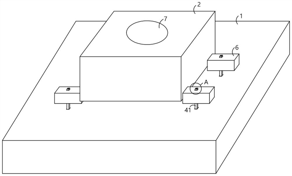
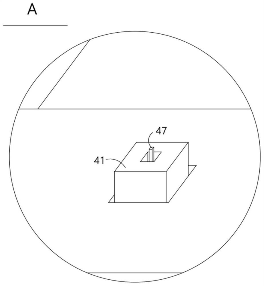
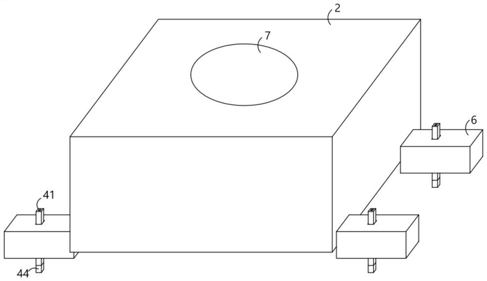
[0043] Considering the particularity of the shape of the femoral stem, a certain amount of lateral stress will be generated inside the femoral stem during the experiment. A loading device for the fatigue test of the hip joint femoral stem includes a base 1, a lateral deflection block 2, a compression plate 3 and The embedding tube 5 used to fix the femoral stem prosthesis 4, where the base 1 is fixed and will not move during the experiment, the compression plate 3 is fixedly installed on the compression device, and the femoral stem prosthesis 4 passes The bone cement is fixed inside the embedding tube 5, and the lateral deflection block 2 is fixedly connected with several fixing plates 6. In this embodiment, four fixing plates 6 are symmetrically arranged on both sides of the lateral deflection block 2, and the lateral deflection block 2 and the base 1 are movably connected by a fixed plate 6, and the fixed plate 6 is fixed on the base 1 during the experiment, thereby realizing...

Embodiment 2

[0045] In this embodiment, when the femoral stem prosthesis 4 is under pressure, the embedding tube 5 drives the femoral stem prosthesis 4 to move in the direction of the lateral stress, thereby realizing the effect of eliminating the internal lateral stress of the femoral stem prosthesis 4, The inside of the side deviation block 2 is provided with a side deviation cavity 8, and the side deviation cavity in this embodiment is set to two, which are respectively arranged on the left and right sides of the placement groove 7, and the inside of the side deviation cavity 8 is provided with a movable plate 9, and the movement The first spring 10 is fixedly connected to the plate 9 and the inner wall of the lateral cavity 8, and the moving plate 9 is fixedly connected to a stabilizing plate 11 which can be moved into the placement groove 7. The stabilizing plate 11 is in movable contact with the embedding tube 5. When the embedding tube 5 When placed inside the placement groove 7, the...

Embodiment 3

[0047] In the existing devices, the fixing of the base 1 and the side deflection block 2 is realized by screws, but the number of times of pressurization in this experiment is very large, and the phenomenon of deviation of the device often occurs as the experiment progresses. This embodiment On the basis of using the fixed plate 6 to fix, the suction cup 12 is set, and the movement of the embedding cylinder 5 in the process of eliminating the lateral stress is used to make the suction cup 12 more and more tightly adsorb the base 1 as the experiment progresses, and the lateral deviation The block 2 is fixedly connected with a suction cup 12 for sucking the base 1. When the fixing plate 6 and the base 1 are fixed, a closed space is formed between the suction cup 12 and the base 1. In this embodiment, two lateral cavities 8 and the suction cup 12 are set. And the subsequent air-blocking assembly is only arranged on one side to form a match with the structure in the side-biasing ch...


PUM


Abstract

A hip joint femoral stem fatigue test loading device provided by the present invention comprises a base, a lateral deviation block, a pressurizing plate and an embedding cylinder, the lateral deviation block is internally provided with a placing groove for movably placing the embedding cylinder, the lateral deviation block is internally and movably provided with a moving plate, the moving plate is fixedly connected with a stabilizing plate movably extending into the placing groove, and the stabilizing plate is fixedly connected with a clamping plate. The stabilizing plate is in movable contact with the embedding cylinder, the fixing plate is fixedly connected with a suction cup used for sucking the base, an inflation cavity and an air bag which are communicated with each other are arranged in the base, the piston plate is fixedly connected with an impact block, and a sound production piece is fixedly arranged in the sound production cavity. In the use process, the embedding cylinder is movably arranged in the placement cavity, so that the lateral stress on the femoral stem prosthesis can be eliminated during pressurization, meanwhile, the lateral deviation block adsorbs the base through the suction cup and the adsorption is tighter and tighter along with the proceeding of an experiment, and meanwhile, when the femoral stem prosthesis turns over and loosens, a sound can be made to remind an operator.

Description

technical field [0001] The invention relates to the technical field of medical fatigue experiments, in particular to a loading device for fatigue experiments of hip joint femoral stems. Background technique [0002] Fatigue performance is a key indicator of the reliability of surgical implants such as artificial joints. Aiming at the problem of artificial hip joint fatigue performance testing, a special artificial joint fatigue testing device was developed. Based on the device, according to the ISO7206 standard, an in vitro fatigue test was carried out for artificial femoral stem products, and the deformation measurement and three-dimensional Reconstruction; In addition, the finite element calculation of the artificial femoral stem in the sample is carried out, and the simulation results are consistent with the deformation obtained in the test; after 5 million cycles of fatigue tests, the device runs smoothly without abnormality, reaching the design reliability standard, It...

Claims


Application Information

Patent Timeline
IPC IPC(8): G01N3/34G01N3/02
CPCG01N3/34G01N3/02G01N2203/0073G01N2203/0676
Inventor 余锐郭小庆焦磊
Owner 合肥熠品医药科技有限公司
Why Eureka
Try Eureka