
Unmanned aerial vehicle-mounted chemical gas infrared detection system

An infrared detection and chemical gas technology, applied in the field of spectral detection, can solve the problems of poor shock resistance, long airborne time, unsuitability, etc., and achieve the effect of good response speed and reduced damage efficiency.

Pending Publication Date: 2022-03-01
KUNMING INST OF PHYSICS
View PDF4 Cites 0 Cited by
  • Summary
  • Abstract
  • Description
  • Claims
  • Application Information

AI Technical Summary

Problems solved by technology

[0002] Traditional airborne "line source" gas detectors must perform two-dimensional scanning of the space in the application of monitoring the distribution of gas on the ground, and the required time in the air is too long
The traditional "surface source" infrared imaging spectrometer uses time-modulated infrared interference spectral imaging technology, and the time-modulated spectral imager is a mechanically scanned single-point infrared Fourier spectroscopy technology, which requires a high-precision moving mirror system. The characteristics lead to poor shock resistance of the system. Currently, it can only be used under laboratory conditions where the platform is still. It is difficult to withstand such a severe vibration environment hovering in the air, and it is not suitable for spectral imaging with high spatial resolution.
In addition, the sampling speed is completely dependent on the mechanical scanning rate of the moving mirror, and the response speed of the system is low, which is not suitable for measuring large-area moving or transient target spectra

Method used


Image

  • Unmanned aerial vehicle-mounted chemical gas infrared detection system
  • Unmanned aerial vehicle-mounted chemical gas infrared detection system
  • Unmanned aerial vehicle-mounted chemical gas infrared detection system

Examples


Embodiment Construction

[0030] In order to make the purpose, content, and advantages of the present invention clearer, the specific implementation manners of the present invention will be further described in detail below in conjunction with the accompanying drawings and implementation examples.

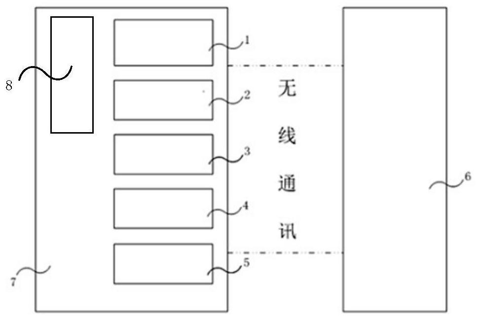
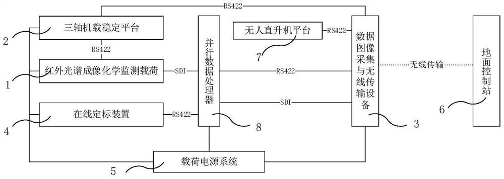
[0031] Such as figure 1 As shown, the UAV-borne chemical gas detection system of the present invention is mainly composed of an infrared spectral imaging chemical monitoring load 1, a three-axis airborne stable platform 2, data image acquisition and wireless transmission equipment 3, an online calibration device 4, and a load power supply system 5. Composed of a parallel data processor 8, a ground control station 6 and an unmanned helicopter platform 7.

[0032] The unmanned helicopter platform 7 is equipped with an infrared spectral imaging chemical monitoring load 1, a three-axis airborne stabilization platform 2, data image acquisition and wireless transmission equipment 3, an online calibration device 4...


PUM


Abstract

The invention discloses an unmanned aerial vehicle-mounted chemical gas infrared detection system which comprises an infrared spectral imaging chemical monitoring load borne by an unmanned aerial vehicle platform, a three-axis airborne stable platform, data image acquisition and wireless transmission equipment, an online calibration device, a parallel data processor, a load power supply system, a ground station and the unmanned aerial vehicle platform. The infrared spectrum imaging chemical monitoring load is mounted on the three-axis airborne stable platform and then mounted on the unmanned aerial vehicle platform, and the data image acquisition and wireless transmission equipment, the online calibration device, the load power supply system and the parallel data processor are mounted on the unmanned aerial vehicle platform. The unmanned aerial vehicle is controlled by the ground station to fly to a target region, when a suspicious cloud cluster is found during cruising, the unmanned aerial vehicle is hovered, gas cloud cluster spectral image monitoring is performed, monitoring information and images are superposed after video image acquisition and onboard data processing, and the superposed information and images are wirelessly transmitted to the ground station and are processed and displayed by the ground station.

Description

technical field [0001] The invention belongs to the field of spectrum detection, and in particular relates to an infrared detection system for unmanned aerial vehicle-borne chemical gases. Background technique [0002] Traditional airborne "line source" gas detectors must perform two-dimensional scanning of the space in the application of monitoring the gas distribution on the ground, which requires too long time in the air. The traditional "surface source" infrared imaging spectrometer uses time-modulated infrared interference spectral imaging technology, and the time-modulated spectral imager is a mechanically scanned single-point infrared Fourier spectroscopy technology, which requires a high-precision moving mirror system. The characteristics lead to poor shock resistance of the system. Currently, it can only be used under laboratory conditions where the platform is stationary, and it is difficult to withstand such a severe vibration environment hovering in the air. It i...

Claims


Application Information

Patent Timeline
Patent Type & Authority Applications(China)
IPC IPC(8): G01N21/3504
CPCG01N21/3504
Inventor 杨智雄王博洋束慧琴张卫锋郑为建雷正刚余春超严敏王红伟张培仲汪凌志胡耀航郑传武袁明尧王国庆丁瑞霖周琴段绍丽庞玲玲李坤管照阳
Owner KUNMING INST OF PHYSICS
Learn More