Register renaming method and system for processor

A register renaming and register technology, applied in the direction of electrical digital data processing, instruments, machine execution devices, etc., can solve the problems of processor cycle time impact, improve processor performance, disadvantages, etc., to increase the overall frequency and reduce the cycle time Time impact, the effect of reducing the critical path delay

Active Publication Date: 2022-04-22
GUANGDONG COMM & NETWORKS INST
View PDF6 Cites 0 Cited by
  • Summary
  • Abstract
  • Description
  • Claims
  • Application Information

AI Technical Summary

Problems solved by technology

[0005] It can be seen that whether the register renaming method implemented in one cycle or two cycles has an impact on the cycle time of the processor, it is not conducive to improving the performance of the processor.

Method used


Image

  • Register renaming method and system for processor
  • Register renaming method and system for processor
  • Register renaming method and system for processor

Examples


Embodiment 1

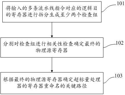
[0033] see figure 2 , figure 2 It is a schematic flowchart of a register renaming method for a processor disclosed by an embodiment of the present invention. Such as figure 2 As shown, the register renaming method for a processor may include the following operations:

[0034] 101. Split logical destination registers corresponding to multiple input pipeline instructions to generate at least two inspection groups.

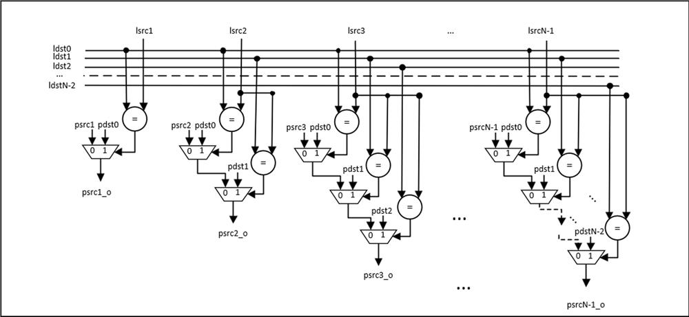
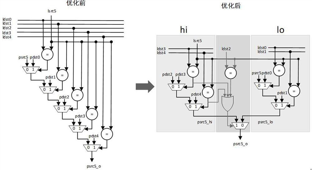
[0035]Since this application is mainly to solve the problem that the renaming critical path is too long when multiple pipeline instructions are in parallel, multiple pipeline instructions are split in advance, and the basis for splitting is to check the composition of the number of pipeline instructions How groups can meet the shortest critical path objective. Therefore, the present application performs different splitting and combining of odd-numbered pipeline instructions and even-numbered pipeline instructions. When the number of pipeline instructions inpu...

Embodiment 2

[0047] see Figure 5 , Figure 5 It is a schematic diagram of a system for register renaming of a processor disclosed by an embodiment of the present invention. Such as Figure 5 As shown, the system for register renaming of a processor includes: a splitting module 1 , a dependency checking module 2 and a critical path determining module 3 .

[0048] The splitting module 1 is used to split the logical destination registers corresponding to the input pipeline instructions to generate at least two inspection groups. The dependency check module 2 is used to perform a dependency check on the check groups respectively to determine the final physical source register. The critical path determination module 3 is used to determine the critical path of register renaming of the superscalar processor according to the final physical source register.

[0049] Splitting module 1 can be implemented as a pre-woven execution program. When the input pipeline instructions are even, the logica...

Embodiment 3

[0054] see Figure 7 , Figure 7 It is a structural schematic diagram of a register renaming device for a processor disclosed by an embodiment of the present invention. Such as Figure 7 As shown, the device may include:

[0055] A memory 601 storing executable program codes;

[0056] an executor 602 coupled to the memory 601;

[0057] The executor 602 invokes the executable program code stored in the memory 601 to execute the register renaming method for a processor described in the first embodiment.


PUM


Abstract

The invention discloses a register renaming method for a processor. The method comprises: splitting logical purpose registers corresponding to multiple input pipeline instructions to generate at least two inspection groups; performing correlation check on the inspection groups respectively A final physical source register is determined; and a critical path for register renaming of the superscalar processor is determined according to the final physical source register. Therefore, the critical path of the register renaming dependency check processing circuit can be optimized, the time delay of the critical path can be reduced, and the frequency of the superscalar processor can be increased.

Description

technical field [0001] The invention relates to the technical field of superscalar processor design, in particular to a register renaming method and system for a processor. Background technique [0002] Register renaming technology is widely used in the back-end pipeline of superscalar processors to increase the number of parallel executions of subsequent instructions. However, register renaming involves correlation checking and processing circuits between multiple instructions, which often takes a certain amount of time to complete, and has a great impact on the cycle time of the entire processor. [0003] At present, the register renaming technology is basically completed in one cycle, including operations such as dependency check and processing, and renaming table update. However, this solution tends to greatly reduce the frequency of the entire processor as the number of parallel instructions increases and the critical path of the dependency check processing circuit inc...

Claims


Application Information

Patent Timeline
Patent Type & Authority Patents(China)
IPC IPC(8): G06F9/30G06F9/38
CPCG06F9/30105G06F9/3867
Inventor 周观太陈钦树朱伏生朱晓明
Owner GUANGDONG COMM & NETWORKS INST
Why Eureka
Try Eureka