
Support-free 3D printing method

A 3D printing, unsupported technology, applied in the field of 3D printing, can solve the problems of increased powder consumption, low manufacturing efficiency, inability to add supports, etc., to shorten the forming time, save powder, and improve the efficiency of 3D printing.

Active Publication Date: 2022-03-04
深圳市华阳新材料科技有限公司
View PDF22 Cites 3 Cited by
  • Summary
  • Abstract
  • Description
  • Claims
  • Application Information

AI Technical Summary

Problems solved by technology

[0002] In the existing technology, laser selective melting forming technology is a commonly used 3D printing process. Because of the technical principle of layer stacking, it is often necessary to add block support to the small angle area of ​​the part to form it. For semi-closed structures, small For workpieces with gaps in size, there may be cases where supports cannot be added or there is not enough space to use tools to remove them after adding supports. At the same time, the way of adding supports will lead to increased powder consumption, longer forming time, and low manufacturing efficiency.

Method used


Image

  • Support-free 3D printing method
  • Support-free 3D printing method
  • Support-free 3D printing method

Examples


Embodiment 1

[0050] In this embodiment, the unsupported 3D printing method can refer to the following steps:

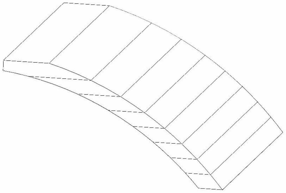
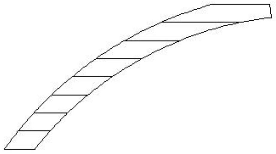
[0051] Step 1, see figure 1 , the present invention is explained by taking a small-angle arc structure as an example, which is defined as: arc body;

[0052] Step 2, define the area where the angle between the inscribed surface of the arc structure and the horizontal direction is less than 45° as the small angle area D;

[0053] Step 3, according to the principle of laser selective melting forming, the parts are formed in a layer-by-layer manner. The layered thickness of each part is defined as d, and d is generally 0.02 to 5 mm. The structure of the arc body after layering is as follows figure 1 , 2 shown;

[0054] Step 4. After the arc body is directly layered, each layer will have sharp edges. Because the part is actually composed of a series of triangular faces, when the layering software recognizes it, the sharp edges will be blunted and form right-angled edges. , so th...


PUM

PropertyMeasurementUnit
thicknessaaaaaaaaaa

Abstract

The invention discloses a support-free 3D printing method, which is characterized in that a currently printed part layer is set as an Nth layer, a next layer to be printed is set as an (N + 1) th layer, in a small-angle area, a part of area of the (N + 1) th layer can exceed a boundary line of the Nth layer, the part of area exceeding the boundary is defined as a suspended area, the suspended width of the suspended area is defined as W, and defining an included angle between a connecting line from the (N + 1) th layer of bottom edge to the Nth layer of bottom edge and the horizontal direction as alpha. The ratio of the laser power P to the laser scanning speed V is adjusted in time in the laser scanning process of the inner side and the outer side of the boundary and the suspension area, when the laser beam scans the (N + 1) th layer of overlapping area, the spot diameter phi of the laser beam is controlled to be kept unchanged or amplified, and after the laser beam scans the (N + 1) th layer of small-angle suspension area and the overlapping area, the laser beam is controlled to be not changed. And the spot diameter phi of the laser beam is controlled to be reduced, and based on the principle, the suspended area and the overlapped area of each part layer can be printed and formed under the condition of not depending on a supporting body.

Description

technical field [0001] The invention relates to a 3D printing method, in particular to an unsupported 3D printing method. Background technique [0002] In the existing technology, laser selective melting forming technology is a commonly used 3D printing process. Because of the technical principle of layer stacking, it is often necessary to add block support to the small angle area of ​​the part to form it. For semi-closed structures, small For workpieces with gaps in size, there may be situations where supports cannot be added or there is not enough space to use tools to remove them after adding supports. At the same time, the way of adding supports will lead to increased powder consumption, longer forming time, and low manufacturing efficiency. Contents of the invention [0003] The technical problem to be solved by the present invention is to provide an unsupported 3D printing method that does not need to add a large number of supports, saves powder, has short forming ti...

Claims


Application Information

Patent Timeline
Patent Type & Authority Applications(China)
IPC IPC(8): B22F10/38B22F10/28B22F10/364B22F10/366B22F10/85B33Y10/00B33Y50/02
CPCB22F10/385B22F10/28B22F10/364B22F10/366B22F10/85B33Y10/00B33Y50/02Y02P10/25
Inventor 韩向阳刘普祥袁浩
Owner 深圳市华阳新材料科技有限公司
Learn More