Mechanical automatic machine tool security and protection device

A technology for driving devices and machine tools, which is applied to metal processing machinery parts, maintenance and safety accessories, and large fixed members, etc. It can solve the problems of scattered impurities, pollution, and inability to filter impurities, so as to improve the use effect, reduce decibels, and facilitate separation effect

Inactive Publication Date: 2022-03-04
HENAN POLYTECHNIC INST
View PDF0 Cites 0 Cited by
  • Summary
  • Abstract
  • Description
  • Claims
  • Application Information

AI Technical Summary

Problems solved by technology

[0004] 1. No noise reduction function, long-term noise pollution will affect human health;
[0005] 2. It is impossible to filter the impurities in the dust, and the impurities are scattered inside the security device, and the cleaning is time-consuming and laborious;
[0006] 3. The installation method between the protective shell and the machine tool is mostly bolted connection, and the maintenance of internal parts is very inconvenient

Method used


Image

  • Mechanical automatic machine tool security and protection device
  • Mechanical automatic machine tool security and protection device
  • Mechanical automatic machine tool security and protection device

Examples


Embodiment 1

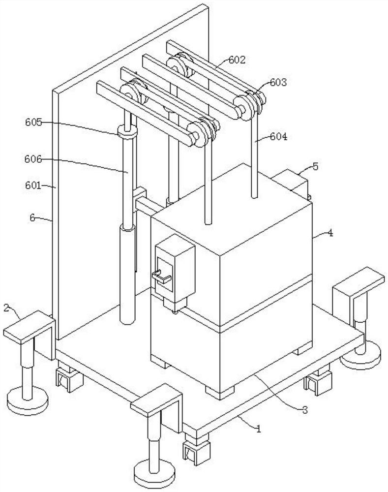
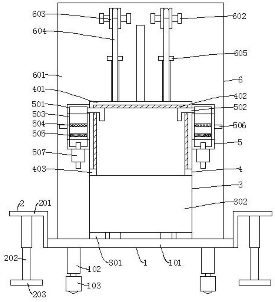
[0050] Such as figure 1 , image 3 , Figure 5 , Figure 7 , Figure 8 As shown, a security device for a mechanical automation machine tool includes a moving mechanism 1 for driving the device to move, a fixing mechanism 2 for fixing the device, and a processing mechanism 3 for processing workpieces. The moving mechanism 1 is installed on both sides There is a fixed mechanism 2, and a processing mechanism 3 is fixed above the moving mechanism 1, which also includes a protective mechanism 4 for preventing noise and dust from endangering human health, a filtering mechanism 5 for filtering dust, and a mechanism for driving the protective shell 401 up and down. The lifting mechanism 6, the protective mechanism 4 is arranged above the processing mechanism 3, the filter mechanism 5 is fixed on both sides of the protective mechanism 4, and the lifting mechanism 6 is arranged at the rear of the protective mechanism 4;

[0051] The protective mechanism 4 includes a protective shell...

Embodiment 2

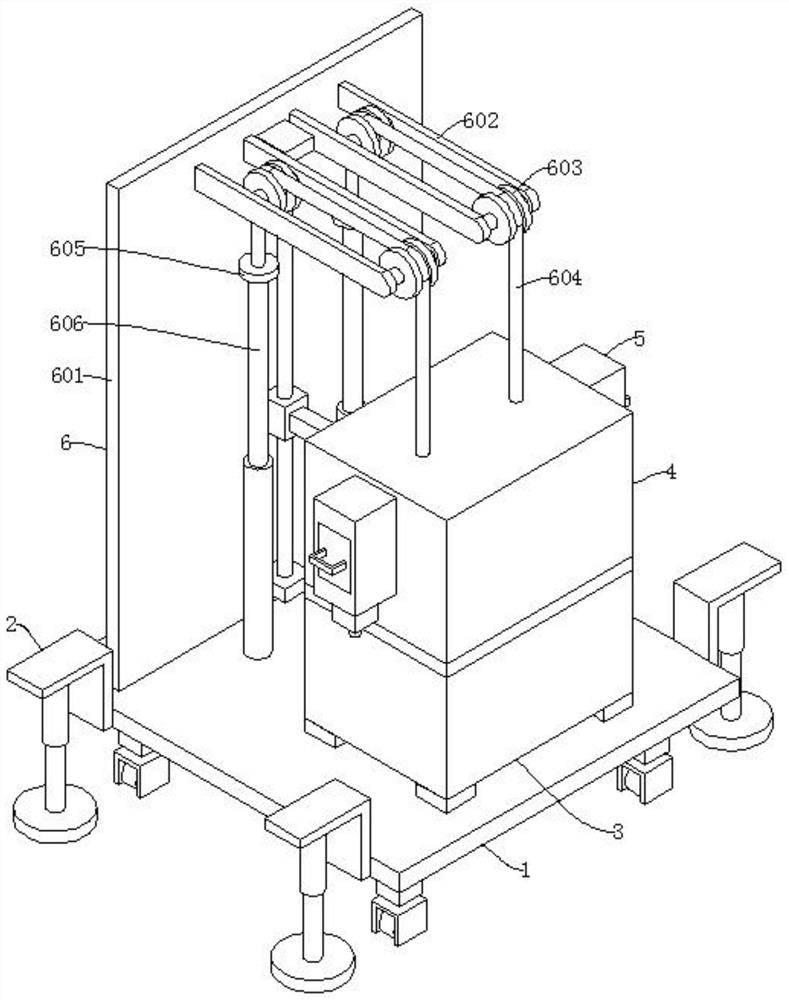
[0057] Such as figure 2 , Figure 4 , Figure 6 , Figure 8 As shown, the difference between Embodiment 2 and Embodiment 1 is that the first vertical plate 6011, the guide hole 6012, the lifting seat 6013, and the first lifting rod 6014 are replaced by the second vertical plate 6015, the guide rod 6016, the end plate 6017, When the lifting sleeve 6018, the second lifting rod 6019, and the internal parts of the protective shell 401 need maintenance, start the second electric push rod 606, and the second electric push rod 606 shrinks to drive the connecting block 605 to descend, and the connecting block 605 descends to drive the traction rope 604 Move, the traction rope 604 drives the protective shell 401 to rise, and the protective shell 401 drives the lifting sleeve 6018 to rise along the guide bar 6016 through the second lifting rod 6019. After the protective shell 401 rises to a certain height, the internal parts can be repaired and maintained.


PUM


Abstract

The invention discloses a mechanical automation machine tool security device which comprises a moving mechanism used for driving the device to move, fixing mechanisms used for fixing the device and a machining mechanism used for machining a workpiece, the fixing mechanisms are installed on the two sides of the moving mechanism, and the machining mechanism is fixed to the upper portion of the moving mechanism. The protection mechanism is used for preventing noise and dust from harming human health, the filtering mechanisms are used for filtering the dust, the lifting mechanism is used for driving the protection shell to ascend and descend, the protection mechanism is arranged above the processing mechanism, and the filtering mechanisms are fixed to the two sides of the protection mechanism. The lifting mechanism is arranged on the rear portion of the protection mechanism. By arranging the protection mechanism, the sound absorption plate can absorb noise generated in the machining process, the decibel of the noise is effectively reduced, and the body health of workers is protected against influences.

Description

technical field [0001] The invention relates to the technical field of mechanical automation, in particular to a security device for a mechanical automation machine tool. Background technique [0002] Mechanical automation machine tools are also called CNC lathes, and CNC lathes are one of the most widely used CNC machine tools. It is mainly used for cutting the inner and outer cylindrical surfaces of shaft parts or disk parts, the inner and outer conical surfaces of arbitrary cone angles, the complex rotary inner and outer curved surfaces, cylinders, and conical threads, etc., and can perform grooving, drilling, reaming, and reaming. Holes and borings etc. The CNC machine tool automatically processes the processed parts according to the pre-programmed processing program. We write the processing route, process parameters, tool trajectory, displacement, cutting parameters and auxiliary functions of the parts into a processing program sheet according to the instruction code ...

Claims


Application Information

Patent Timeline
Patent Type & Authority Applications(China)
IPC IPC(8): B23Q11/00B23Q11/08B23Q1/25
CPCB23Q11/00B23Q11/0096B23Q11/0046B23Q11/08B23Q1/25
Inventor 赵岩梁硕张海滨淮鹏陆正芳李旗冯佩佩刘天恒叶向博陈天宇薛冰冰杨登坡杨一鸣齐兆婕赵奕飞
Owner HENAN POLYTECHNIC INST
Why Eureka
Try Eureka