Traction device for large-size pipe fitting

A traction device and large-scale technology, applied in the traction field, can solve the problems of single transportation mode, inconvenient protective running structure, pipe fittings detaching from device control, etc., and achieve the effects of improving stability, maintaining stability and avoiding deflection.

Pending Publication Date: 2022-03-04
江苏高路复合材料有限公司
View PDF1 Cites 0 Cited by
  • Summary
  • Abstract
  • Description
  • Claims
  • Application Information

AI Technical Summary

Problems solved by technology

[0005] Aiming at the deficiencies of the prior art, the present invention provides a traction device for large-sized pipe fittings, which solves the problem that the pipe fitting traction and rotation precision processing device proposed in the above-mentioned background technology has a single transportation mode during use and is inconvenient to provide protection for pipe fittings. operating structure, and easily lead to the problem that the pipe fittings are out of the control of the device

Method used


Image

  • Traction device for large-size pipe fitting
  • Traction device for large-size pipe fitting
  • Traction device for large-size pipe fitting

Examples


Embodiment 1

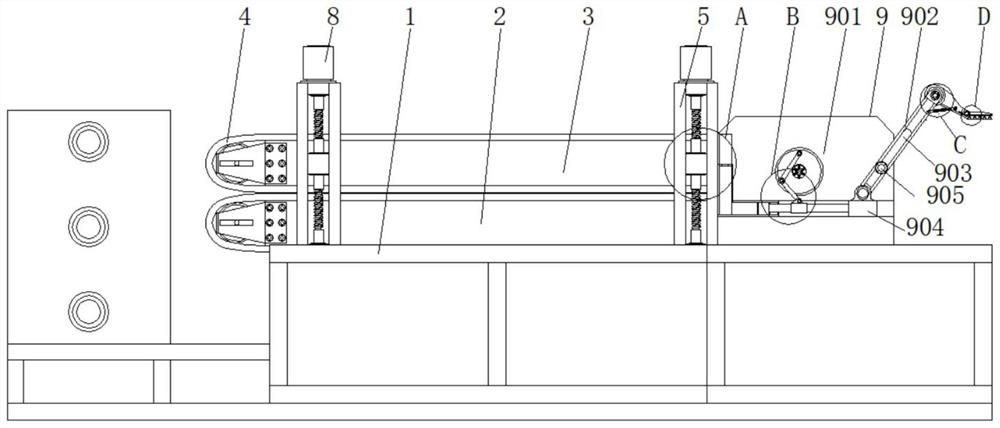
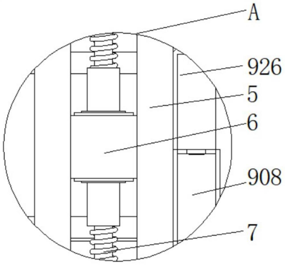
[0029] like figure 1As shown, this embodiment proposes a traction device for large-sized pipe fittings, including a bottom support cabinet frame 1, a bottom transmission mechanism 2 installed on the bottom support cabinet frame 1, a fixed frame 3 installed on the bottom transmission mechanism 2, And the conveyor belt 4 installed on the fixed frame 3, two groups of position adjustment mechanisms are arranged on both sides of the fixed frame 3, each group has two, and the position adjustment mechanism includes a guide frame 5, a guide fixed block 6, an adjustment screw rod 7 and a linear wire The rod motor 8 and the guide frame 5 are fixed on the bottom supporting cabinet frame 1 by bolts, the guide frame 5 is provided with an adjusting screw 7, and the input end of the adjusting screw 7 is connected with a linear screw motor 8, and the linear screw motor Under the action of 8, the guide fixing block 6 can be moved along the central axis direction of the guide frame 5 by adjusti...

Embodiment 2

[0031] The solution in Embodiment 1 will be further introduced in combination with specific working methods below, see the following description for details:

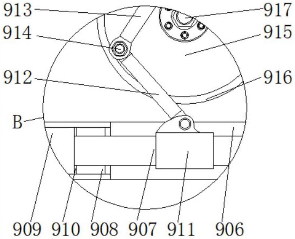
[0032] like figure 1 , figure 2 , image 3 , Figure 4 and Figure 5 As shown, as a preferred embodiment, on the basis of the above method, further, the auxiliary traction and pushing mechanism 9 includes an installation frame 901, a support arm 902, a chute 903, an adjustment guide block 904, a fixed sliding pin 905, and a transverse chute 906, connecting slide bar 907, cavity post 908, piston block 909, rubber gasket 910, fixed sleeve post 911, connecting strut 912, adjusting strut 913, connecting pin 914, turntable 915, ring frame 916, drive motor 917 , pressing plate 918, fixed shaft 919, connecting spring 920, wear-resistant rubber pad 921, pull plate 922, return coil spring 923, lock shaft 924, suction cup 925 and rubber airbag 926, and the bottom supporting cabinet frame 1 is provided with an installation fr...


PUM


Abstract

The invention discloses a large-size pipe fitting traction device, and relates to the technical field of traction, in particular to a large-size pipe fitting traction device which comprises a bottom supporting cabinet frame, a bottom layer conveying mechanism installed on the bottom supporting cabinet frame, a fixed frame installed on the bottom layer conveying mechanism and a conveying belt installed on the fixed frame. Two sets of position adjusting mechanisms are arranged on the two sides of the fixing frame, each set comprises two position adjusting mechanisms, each position adjusting mechanism comprises a guide frame, a guide fixing block, an adjusting lead screw and a linear lead screw motor, and the guide frames are fixed to the bottom supporting cabinet frame through bolts. When the arranged adjusting guide block moves in the direction of the horizontal center line of the transverse sliding groove, due to the fact that the adjusting guide block is movably connected with the supporting arm in a pin mode, one end of the supporting arm can be pulled to move, at the moment, the supporting arm rotates along the outer portion of the fixed sliding pin and synchronously slides along the inner track of the sliding groove, and therefore the rotating angle of the supporting arm can be effectively changed; and the length of the support arm relative to the two sections of the fixed sliding pin can be changed.

Description

technical field [0001] The invention relates to the technical field of traction, in particular to a traction device for large-size pipe fittings. Background technique [0002] Carbon fiber composite pipe is made by pultrusion molding process. Firstly, the mandrel is woven with carbon fiber, and then the resin is injected into the mold, and then quickly cured. While curing, it is pulled. After the pipe is drawn to a certain length, the pipe can be cut to obtain the product. , and in order to ensure the smooth progress of product production, a traction device for large-size pipe fittings is needed. [0003] Aiming at the patent application number CN208132582U of the pipe fitting traction and rotation precision machining device, the utility model discloses a pipe fitting traction rotation precision machining device, which includes a pipe support walking mechanism, a pipe processing mechanism and a pipe fixing traction mechanism; the pipe fixing traction mechanism includes a cla...

Claims


Application Information

Patent Timeline
Patent Type & Authority Applications(China)
IPC IPC(8): B29C70/52B29L23/00
CPCB29C70/527B29L2023/22
Inventor 杨金李麒阳刘昊森
Owner 江苏高路复合材料有限公司
Why Eureka
Try Eureka