Prefabricated berthing component installation supporting structure and installation method

A technology for ship-retaining components and supporting structures is applied in the field of prefabricated ship-receiving components installation and support structures, which can solve the problems of troublesome construction of ship-receiving components and complicated supporting structures, and achieves simple and convenient pouring and molding, simple supporting structure, and reduced construction difficulty. Effect

Pending Publication Date: 2022-03-04
中交二航局第一工程有限公司
View PDF6 Cites 2 Cited by
  • Summary
  • Abstract
  • Description
  • Claims
  • Application Information

AI Technical Summary

Problems solved by technology

[0005] The main purpose of the present invention is to provide a prefabricated installation support structure and installation method for ship-based components, which solves the problems of troublesome construction and complicated support structures for ship-based components

Method used


Image

  • Prefabricated berthing component installation supporting structure and installation method
  • Prefabricated berthing component installation supporting structure and installation method
  • Prefabricated berthing component installation supporting structure and installation method

Examples


Embodiment 1

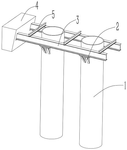
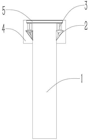
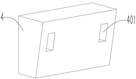
[0031] like Figure 1~8 As shown, a prefabricated ship berthing member installation support structure and installation method, including a ship berthing member 4 and a steel pipe pile 1, is characterized in that: the two sides of the end surface of the ship berthing member 4 are provided with grooves 401, the Both sides of the steel pipe pile 1 are fixed with a support frame 2, and an I-beam 3 is arranged on the support frame 2. One end of the I-beam 3 rests in the groove 401, and the other end of the I-beam 3 is provided with a balance fixing mechanism. With this structure, the groove 401 is reserved when pouring the berth member 4, and the pouring molding is simple and convenient, without affecting the strength of the berth member 4. The I-beam 3 is fixed on the support frame 2, and the end of the I-beam 3 is inserted into the In the groove 401, the ship berth member 4 is supported and fixed, and the stability of the I-beam 3 is ensured by a balanced fixing mechanism.

[00...

Embodiment 2

[0038] In conjunction with Example 1, such as Figure 1~8 As shown, the steel pipe pile 1 is constructed and installed on the bank; the fixed support frame 2 is installed on both sides of the steel pipe pile 1; the I-beam 3 and the beam 5 are installed on the support frame 2; The end of the I-beam 3, the end of the I-beam 3 leans against the groove 401 of the ship member 4; the bottom support system of the pile cap 6 is installed on the I-beam 3; the concrete for the pile cap 6 is poured, and the concrete is connected by Ship component 4; after the concrete is solidified, remove the I-beam 3, the beam 5 and the support frame 2.


PUM


Abstract

The invention provides a prefabricated berthing component installation supporting structure and an installation method, which comprises a berthing component and a steel pipe pile, and is characterized in that grooves are formed in two sides of one end face of the berthing component, supporting frames are fixedly arranged on two sides of the steel pipe pile, I-shaped steel is arranged on the supporting frames, one end of the I-shaped steel abuts against the interiors of the grooves, and the other end of the I-shaped steel abuts against the steel pipe pile. Balance fixing mechanisms are arranged at the other ends of the I-beams. A plurality of grooves are reserved in one side of the berthing component formed through pouring, so that the berthing component is supported by inserting I-shaped steel into the grooves, the supporting structure is simple, mounting and dismounting are easy and convenient, the problem that the strength of the berthing component is affected by corrosion of a pre-buried supporting rod is solved, the reserved grooves do not affect the strength of the berthing component, and the berthing component is convenient to mount and dismount. Pouring forming is simple and convenient, so that construction difficulty is greatly reduced, and operation efficiency is improved.

Description

technical field [0001] The invention relates to the technical field of ships, in particular to a prefabricated ship berthing component installation support structure and an installation method. Background technique [0002] Most of the concrete docking components of the wharf are prefabricated in advance, installed in place on site, and poured together with the beam concrete to form the overall structure of the wharf beam. However, due to the heavy weight of the concrete berthing components, there is no mature supporting platform in the prior art, which leads to difficulties in installation of the concrete berthing components, inconvenience in construction, and potential safety hazards. [0003] Chinese patent "CN109853478B" relates to an installation process of supporting steel beams for berthing components. In this patent, the berthing components are supported from the bottom by supporting mounting plates, but the supporting mounting plates need to be connected with steel ...

Claims


Application Information

Patent Timeline
Patent Type & Authority Applications(China)
IPC IPC(8): E02B3/20
CPCE02B3/20
Inventor 李子侠谭永安伍孝峰赵嵩谢鹏许环智余飞余杨明
Owner 中交二航局第一工程有限公司
Why Eureka
Try Eureka