Support method of swing type anti-seismic recoverable anchor rod suitable for complex slope support

An anchor rod and slope technology, applied in excavation, climate change adaptation, construction, etc., can solve the problems of slope rock and soil collapse, failure of anchoring, etc.

Active Publication Date: 2022-03-04
DALIAN UNIV OF TECH
View PDF6 Cites 0 Cited by
  • Summary
  • Abstract
  • Description
  • Claims
  • Application Information

AI Technical Summary

Problems solved by technology

No matter what kind of failure occurs, it will lead to anchora

Method used


Image

  • Support method of swing type anti-seismic recoverable anchor rod suitable for complex slope support
  • Support method of swing type anti-seismic recoverable anchor rod suitable for complex slope support
  • Support method of swing type anti-seismic recoverable anchor rod suitable for complex slope support

Examples


Embodiment 1

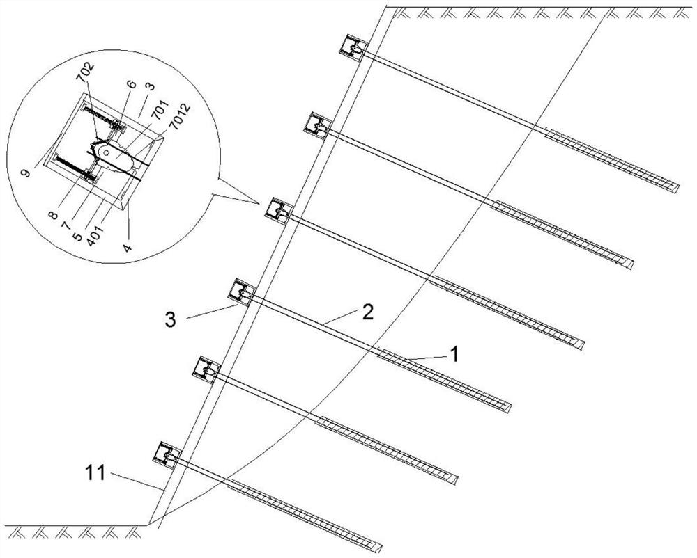
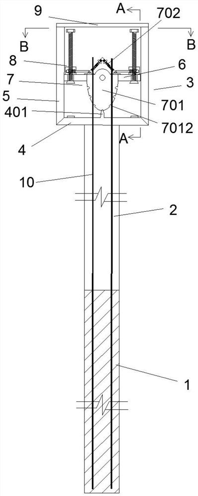
[0042] Such as figure 1 , 2, 3, 4, 5, 6, and 7, a support method for a rocking-type aseismic-recoverable bolt applicable to complex slope support, the rocking-type aseismic-restorable bolt includes anchoring section 1, free Segment 2 and Anchor Head 3. The anchor head 3 includes a backing plate 4, a rigid sliding wall 5, an anchor 6, an anti-seismic device 7, an anchor lifting device 8 and a cover plate 9, and the center of the backing plate 4 is provided with a raised stopper 401, The anchor 6 is nested in the rigid sliding wall 5 and is slidably connected with the rigid sliding wall 5. The middle part of the anchor 6 is provided with a strip-shaped through hole 601, and the anchor 6 is located above the central part of the strip-shaped through hole 601. Middle indicator 602 is indicated.

[0043] The anchorage 6 is provided with several uniform and symmetrically distributed circular through-holes. The number, diameter and distribution of the circular through-holes should ...

Embodiment 2

[0060] After the rocking earthquake-resistant recoverable bolt in Example 1 is damaged by an earthquake, the following steps should be followed for recovery:

[0061] Step 1: Anchor sealing and unsealing, when the anchor is unsealed, the anchor head 3 is protected from damage;

[0062] Step 2: reset the anti-seismic device 7;

[0063] Step 3: Second anchor sealing.

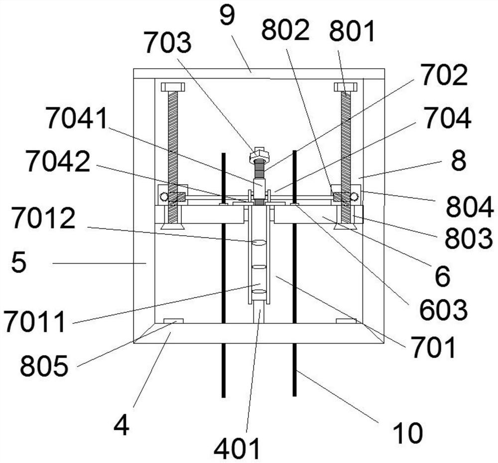
[0064] In the second step, the lifting screw 801 is rotated to the bottom, and the lifting screw 801 is continued to be rotated, the anchorage 6 is held up, the anti-seismic device 7 is in a suspended state, and the nuts a703 on both sides of the upper screw structure 702 are rotated to the screw At the bottom end, lock the anti-seismic device 7 at the balance position, reset the anti-seismic device 7, and then rotate the lifting screw 801 to the top. During the rising process of the lifting screw 801, the stopper 401 and the lower semi-elliptical cutter head 701 are at the highest position. The limiting slots 7...


PUM


Abstract

The invention discloses a supporting method of a swing type anti-seismic recoverable anchor rod suitable for complex slope supporting, the anchor rod structure comprises an anchoring section, a free section and an anchor head, and the anchor head comprises a base plate, a rigid sliding wall, an anchorage device, an anti-seismic device and an anchorage device lifting device. The slope supporting method comprises the following steps: 1, drilling holes; 2, loading an anchor; 3, grouting maintenance; 4, constructing a retaining wall or a surface layer; 5, mounting an anchor head; and 6, tensioning and locking. The method further comprises the step of unsealing after earthquake disasters. And resetting the anti-seismic device. The method effectively solves the problems that in a traditional slope reinforcing method, an anchor rod cannot resist earthquake loads and is damaged or failed in anchoring, so that a slope rock-soil body collapses and slides down, and the method is advanced in anti-seismic concept, excellent in anti-seismic performance and high in anti-seismic performance. The side slope supporting method of the swing type anti-seismic recoverable anchor rod is suitable for complex side slope supporting, can achieve graded anti-seismic and secondary recovery after an earthquake, and has wide application prospects and remarkable economic and social benefits.

Description

technical field [0001] The invention belongs to the technical field of slope reinforcement, and in particular relates to a support method for a swing-type anti-seismic recoverable bolt suitable for complex slope support. Background technique [0002] Landslide disasters occur frequently on steep and complex slopes, and landslide accidents can cause serious adverse consequences, such as: blocking traffic, forming surges, and even burying villages, causing heavy casualties and huge property losses. Therefore, slope reinforcement is required. Nowadays, common reinforcement methods mainly include lattice bolt reinforcement, anchor shotcrete reinforcement, etc. These reinforcement methods are simple and convenient to operate and have obvious effects, but they cannot resist earthquake disasters. [0003] When the earthquake damage strikes, the earthquake action causes the internal force of the bolt to increase sharply, which is very prone to damage. The failure forms are mainly ...

Claims


Application Information

Patent Timeline
IPC IPC(8): E02D17/20E02D5/74E02D27/34
CPCE02D17/20E02D5/74E02D27/34E02D2250/0046E02D2600/30Y02A10/23
Inventor 高幸贾金青陈湘生梅国雄包小华张丽华
Owner DALIAN UNIV OF TECH
Why Eureka
Try Eureka