
Optical fiber communication testing device based on 5G high-reliability and low-delay communication bearer network

A technology of optical fiber communication and testing equipment, applied in transmission monitoring/testing/fault measurement systems, electromagnetic wave transmission systems, electrical components, etc., can solve problems affecting detection efficiency, difficulty in testing components, low delay, etc., and achieve simple and efficient detection , Simple operation, less inconvenience

Pending Publication Date: 2022-03-04
山东华汉电子有限公司
View PDF7 Cites 0 Cited by
  • Summary
  • Abstract
  • Description
  • Claims
  • Application Information

AI Technical Summary

Problems solved by technology

[0002] 5G communication equipment is a new generation of broadband mobile communication technology with high speed, low delay and large connection characteristics. Low latency and effective transmission. In 5G communication equipment, optical fibers are widely used in the connection between RRU modules and communication cabinets for signal transmission. In the study of optical fiber physical characteristics, the optical transmittance test of optical fibers is particularly important, often through the One end of the optical fiber is irradiated with laser light, and the other end is observed to see whether the light is transmitted. During the laser irradiation process of the optical fiber head of the fiber optic FC, ST, and SC models, the fiber head is connected to the laser emitting head for irradiation, and manual alignment is required. After alignment, due to the different head models, it is difficult to adapt the test components one by one. There is a need for manual handling, which brings inconvenience and seriously affects the detection efficiency. Therefore, the existing test components are more cumbersome and inconvenient in the test process. low

Method used


Image

  • Optical fiber communication testing device based on 5G high-reliability and low-delay communication bearer network
  • Optical fiber communication testing device based on 5G high-reliability and low-delay communication bearer network
  • Optical fiber communication testing device based on 5G high-reliability and low-delay communication bearer network

Examples


Embodiment Construction

[0036] The following description serves to disclose the present invention to enable those skilled in the art to carry out the present invention. The preferred embodiments described below are only examples, and those skilled in the art can devise other obvious variations.

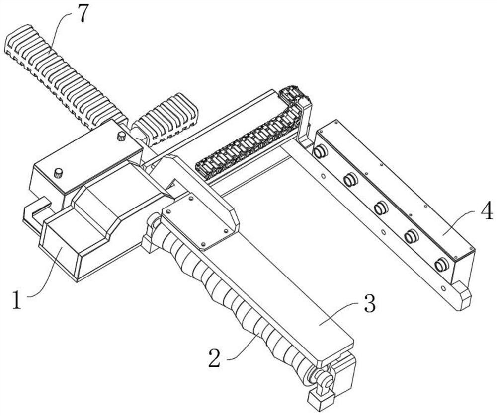
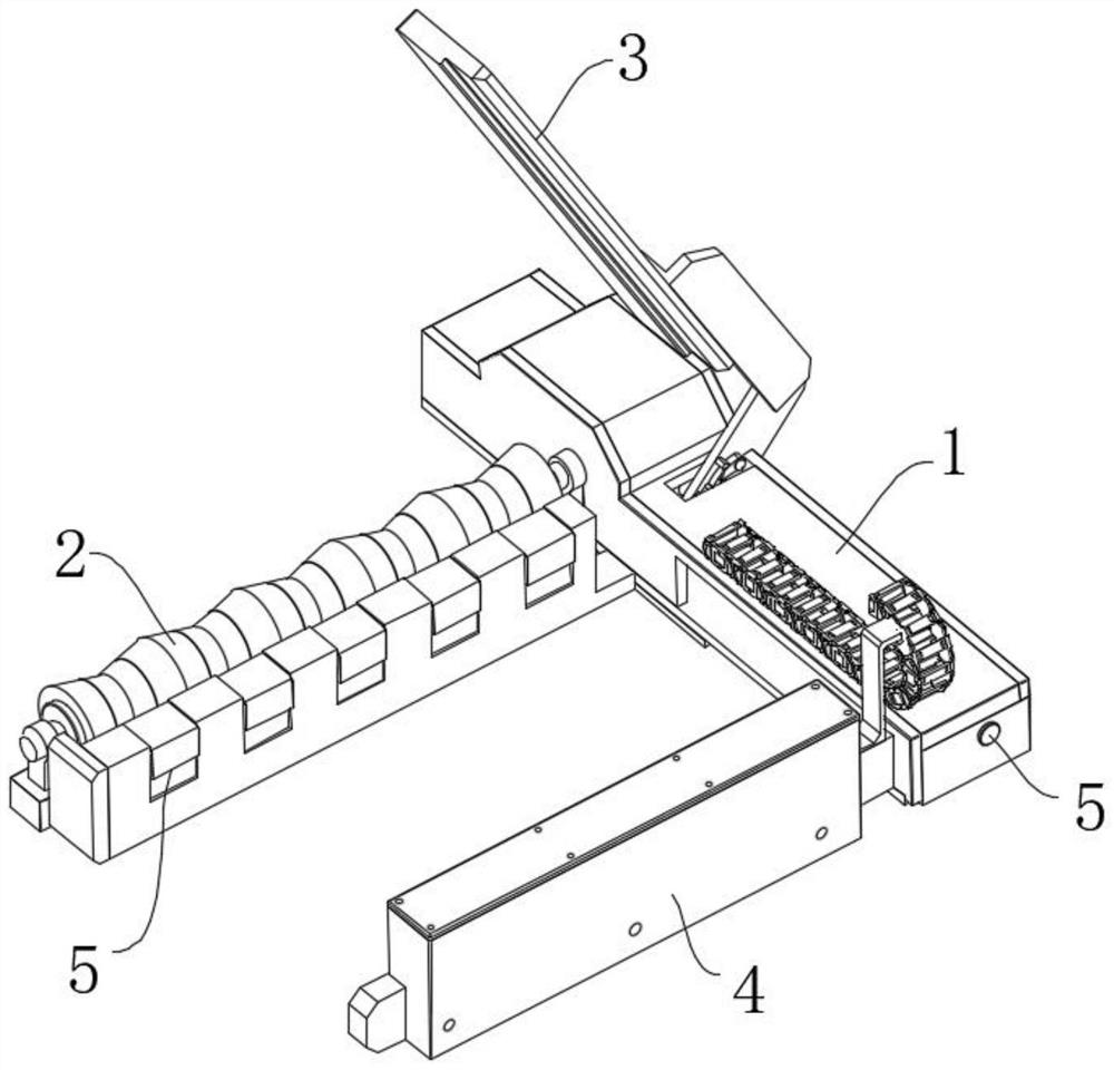
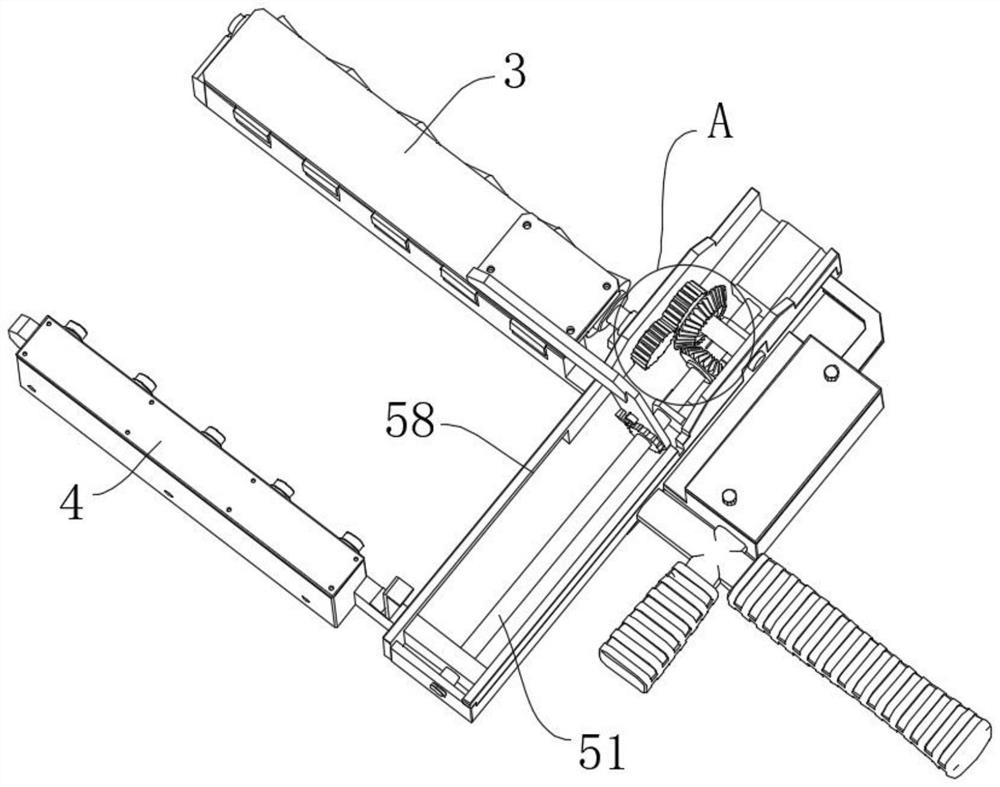
[0037] Such as Figure 1-Figure 15 A fiber optic communication testing device based on a 5G high-reliability and low-delay communication bearer network is shown, including a connecting frame 1, a clamping mechanism 6 is fixedly installed on one side of the connecting frame 1, and one side of the external surface of the connecting frame 1 Close to the rear of the clamping mechanism 6, there is a separation roller mechanism 2 that is rotatably connected, and the outer surface of one side of the connecting frame 1 is slidably installed with a laser emitting mechanism 4 along the front and rear direction, and the laser emitting mechanism 4 is located in front of the clamping mechanism 6. The upper end surface o...


PUM


Abstract

The invention relates to the technical field of optical fiber detection, in particular to an optical fiber communication testing device based on a 5G high-reliability and low-delay communication bearing network, which comprises a connecting frame, a clamping mechanism is fixedly mounted on the outer surface of one side of the connecting frame, and a separation roller mechanism is rotatably connected to the outer surface of one side of the connecting frame close to the rear part of the clamping mechanism. A clamping mechanism is installed on the outer surface of one side of the connecting frame, a laser emitting mechanism is installed on the outer surface of one side of the connecting frame in a sliding mode in the front-back direction, the laser emitting mechanism is located in front of the clamping mechanism, and a pressure limiting mechanism pressed above the separation roller mechanism and the clamping mechanism is rotatably installed on the upper end face of the connecting frame. According to the optical fiber transmission detection device, transmission detection of a plurality of optical fibers can be carried out simultaneously, separation, traction and head fixing of the optical fibers are automatically carried out in the detection process, alignment irradiation of a laser emission head is automatically carried out finally, all steps can be completed only through single-hand operation, detection is simple and efficient, and convenience is brought.

Description

technical field [0001] The invention relates to the technical field of optical fiber detection, in particular to an optical fiber communication testing device based on a 5G high-reliability and low-delay communication bearer network. Background technique [0002] 5G communication equipment is a new generation of broadband mobile communication technology with high speed, low delay and large connection characteristics. Low latency and effective transmission. In 5G communication equipment, optical fibers are widely used in the connection between RRU modules and communication cabinets for signal transmission. In the study of optical fiber physical characteristics, the optical transmittance test of optical fibers is particularly important, often through the One end of the optical fiber is irradiated with laser light, and the other end is observed to see whether the light is transmitted. During the laser irradiation process of the optical fiber head of the fiber optic FC, ST, and ...

Claims


Application Information

Patent Timeline
IPC IPC(8): H04B10/073H04B10/07
CPCH04B10/0731H04B10/07
Inventor 周文奇黄彩琳刘婕赵德军
Owner 山东华汉电子有限公司
Features
  • Generate Ideas
  • Intellectual Property
  • Life Sciences
  • Materials
  • Tech Scout
  • Unparalleled Data Quality
  • Higher Quality Content
  • 60% Fewer Hallucinations
Learn More