Assembly line detection equipment for carrying out quality detection through CCD (Charge Coupled Device) image acquisition

A technology for image acquisition and detection equipment, which is applied to structural parts of electrical equipment, cooling/ventilation/heating transformation, rack/frame structure, etc. , avoid dust accumulation, accelerate the effect of heat dissipation efficiency

Pending Publication Date: 2022-03-04
深圳市华安泰智能科技有限公司
View PDF1 Cites 0 Cited by
  • Summary
  • Abstract
  • Description
  • Claims
  • Application Information

AI Technical Summary

Problems solved by technology

[0006] The main purpose of the present invention is to provide an assembly line inspection equipment for quality inspection through CCD image acquisition, to solve the problem of dust accumulation and dust on the inspection point or on the CCD camera during the operation of the assembly line, which affects the use of the CCD camera

Method used


Image

  • Assembly line detection equipment for carrying out quality detection through CCD (Charge Coupled Device) image acquisition
  • Assembly line detection equipment for carrying out quality detection through CCD (Charge Coupled Device) image acquisition
  • Assembly line detection equipment for carrying out quality detection through CCD (Charge Coupled Device) image acquisition

Examples


Embodiment 1

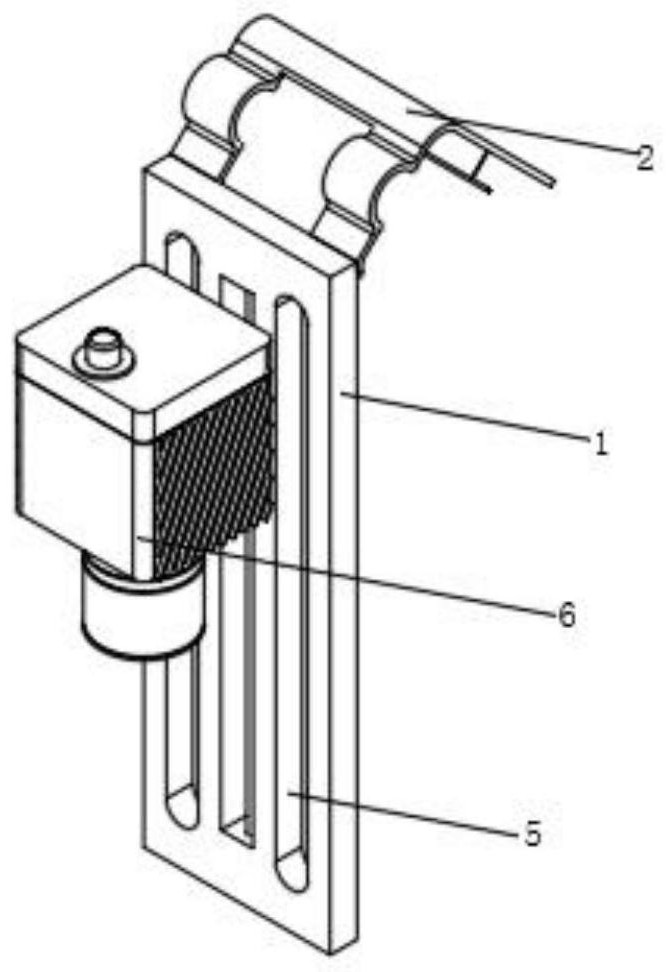
[0033] Such as figure 1 , 2 , 3, 4, and 6, a pipeline inspection device for quality inspection through CCD image acquisition, including a support frame 1 of the driving device, a sliding connector 4, a rectangular through groove 5 and a CCD image acquisition device 6, the driving device The end face of the support frame 1 is provided with three rectangular through grooves 5, and a slide bar is arranged in the middle rectangular through groove 5 of the support frame 1 of the driving device. The shaft of the slide bar is provided with a sliding connector 4, the other end of which is A CCD image acquisition device 6 is provided;

[0034] The upper end of the support frame 1 of the driving device is provided with an angle-adjustable blowing device 2, and the angle-adjusting blowing device 2 is aligned with the CCD image acquisition device 6 to blow air, and the two sides of the CCD image acquisition device 6 are provided with heat dissipation mechanisms for the image acquisition ...

Embodiment 2

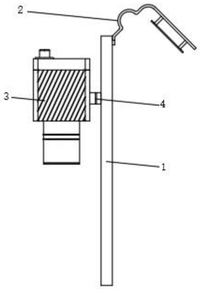
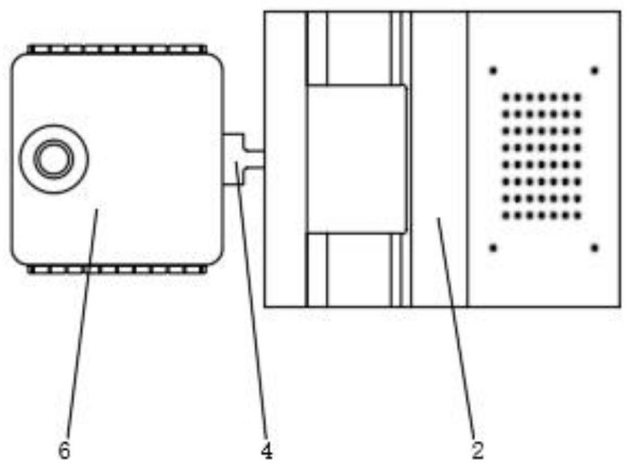
[0038] Such as figure 1 , 4 , 5, and 6, wherein the same or corresponding components as those in Embodiment 1 use the corresponding reference numerals as in Embodiment 1. For the sake of simplicity, only the differences from Embodiment 1 will be described below. The difference is that the heat dissipation mechanism 3 of the image acquisition device includes a heat dissipation plate 301, a heat-conducting circular disc 302 and an inclined heat dissipation fin 303, and the two sides of the CCD image acquisition device 6 are provided with a heat dissipation plate 301, and the heat dissipation plate 301 is facing The end face of the CCD image acquisition device 6 is provided with a heat-conducting circular disk 302, and the other end of the heat dissipation plate 301 is provided with an inclined heat dissipation fin 303;

[0039] The heat dissipation plate 301 and the inclined heat dissipation fins 303 are integrally arranged, the heat dissipation plate 301 is fixedly connected w...

Embodiment 3

[0041] Such as Figure 5 As shown, the components that are the same as or corresponding to those in the first embodiment are marked with the corresponding reference numerals in the first embodiment. For the sake of simplicity, only the differences from the first embodiment will be described below. The difference is that a plug is provided between the heat dissipation plate 301 and the heat conduction circular disk 302 , and the heat dissipation plate 301 and the heat conduction circular disk 302 are connected with the CCD image acquisition device 6 through the bolts.


PUM


Abstract

The invention relates to the technical field of assembly line detection, in particular to assembly line detection equipment for quality detection through CCD image acquisition, and aims to solve the problem that the use of a CCD camera is affected by dust accumulation and raised dust on a detection point or the CCD camera during assembly line operation. According to the technical scheme, the air blowing device with the angle adjusting function comprises an additional fixing plate, small heat dissipation holes, arc-shaped folding strips, a rectangular-ambulatory-plane mounting frame and a heat dissipation fan, and the arc-shaped folding strips are arranged at the upper end of a supporting frame of a driving device; the cooling fan is aligned with the rectangular through groove and the CCD image acquisition device, dust on the CCD image acquisition device can be blown out, dust accumulation of the CCD image acquisition device caused by assembly line operation is avoided, blowing heat dissipation can be conducted on the CCD image acquisition device, and then the blowing direction of the cooling fan is adjusted, so that the CCD image acquisition device can be cooled. The cooling fan is aligned with detection points on the assembly line to blow air in and out, sundries at the detection points on the assembly line can be blown out, and inaccurate detection is avoided.

Description

technical field [0001] The invention relates to the technical field of assembly line inspection, in particular to an assembly line inspection device for quality inspection through CCD image acquisition. Background technique [0002] CCD camera is in the security system. The generation of image is mainly from CCD camera at present. CCD is the abbreviation of charge coupled device, which can convert light into charge and store and transfer the charge, and can also take out the stored charge to generate voltage. Therefore, it is an ideal CCD camera component, and the CCD camera it constitutes is widely used because of its small size, light weight, unaffected by magnetic fields, and anti-vibration and impact characteristics; [0003] The Chinese utility model patent application number is CN201320413004.3, and the patent name is a CCD sliding table sorting system, including a feeding system, an X-Y handling system, a CCD image acquisition and recognition system and a mechanical l...

Claims


Application Information

Patent Timeline
Patent Type & Authority Applications(China)
IPC IPC(8): H05K7/20H05K7/18
CPCH05K7/20136H05K7/18H05K7/20172
Inventor 岑兆祥王意
Owner 深圳市华安泰智能科技有限公司
Why Eureka
Try Eureka