Eye medicine dropping device for department of pediatrics
A medicine drop and eye technology, applied in ophthalmology treatment, etc., can solve problems such as difficult fixation, device touching children's eyes, small structure, etc.
- Summary
- Abstract
- Description
- Claims
- Application Information
AI Technical Summary
Problems solved by technology
Method used
Image
Examples
Embodiment 1
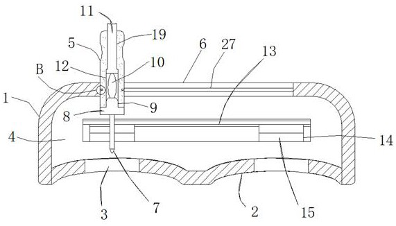
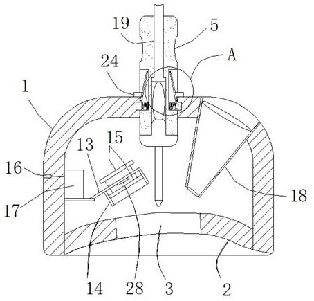
[0036] A pediatric eye medicine dropper, comprising a medicine dropper body 1, on both sides of the lower end surface of the medicine dropper body 1 are provided eye corresponding grooves 2 for contacting children's eyes, and the middle part of the eye corresponding groove 2 is opened There is a watch hole 3 for dropping medicine, and the inside of the medicine dropper body 1 is provided with an inner cavity 4, and a vertically arranged medicine drop tube 7 is arranged in the inner cavity 4 directly above the watch hole 3, which is used for treating children's eyes. Carry out the medicine drop, the side of the medicine drop tube 7 above the side of the eye hole 3 is provided with a visible belt assembly 15 that induces children to observe, and is used to attract children's attention and keep the children's eyes open. The medicine dropper body 1 The middle part of the upper end of the upper end is provided with a transposition sliding port 6 communicating with the inner cavity 4...
Embodiment 2
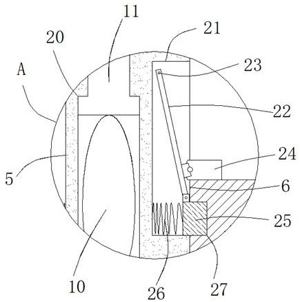
[0038]The difference between this embodiment and Embodiment 1 is that the middle part of both sides of the dripping structure 5 is provided with an adjustment groove 21, and the inside of the adjustment groove 21 is provided with a rotatable deflection rod 22, and the upper end of the deflection rod 22 is adjusted by a rotating shaft 23. The inner wall of the groove 21 is connected so that the deflection rod 22 rotates around the rotating shaft 23. The bottom of the deflection rod 22 is connected with the push head 24 through the rotation shaft. The push head 24 can drive the deflection rod 22 to rotate in the adjustment groove 21, and the push head 24 The end of the deflection rod 22 below is connected with the limit slider 25 through the rotating shaft. When the deflection rod 22 rotates, it can drive the limit slider 25 to move. A spring 26 is arranged between the limit slider 25 and the adjustment groove 21. The limit slider 25 is correspondingly arranged with the guide gro...
Embodiment 3
[0040] The difference between this embodiment and Embodiment 1 is that the inside of the sliding port 19 is pierced with an inverted "T"-shaped structure for pressing down the drug delivery rod 11, and the protruding part of the bottom end of the sliding port 19 is located inside the extrusion chamber 12, and the extrusion chamber 12 and the junction of the sliding port 19 are provided with a limiting groove 20 for limiting the downward pressure of the drug delivery rod 11, the extrusion chamber 12 communicates with the sliding port 19, and the diameter of the extrusion chamber 12 is greater than the diameter of the sliding port 19, so as to realize the downward pressure on the drug rod 11. Press the limit of the protruding part of the lower end of the drug delivery rod 11 to prevent the downward pressure of the drug delivery rod 11 from moving out of the sliding port 19. The lower opening of the dripping structure 5 is connected with the threaded joint 9 on the upper end of the...
PUM
 Abstract
Description
Claims
Application Information
 - R&D
- Intellectual Property
- Life Sciences
- Materials
- Tech Scout
- Unparalleled Data Quality
- Higher Quality Content
- 60% Fewer Hallucinations
Browse by: Latest US Patents, China's latest patents, Technical Efficacy Thesaurus, Application Domain, Technology Topic, Popular Technical Reports.
© 2025 PatSnap. All rights reserved.Legal|Privacy policy|Modern Slavery Act Transparency Statement|Sitemap|About US| Contact US: help@patsnap.com


