
Steel belt hobbing beveling machine and steel belt hobbing beveling process

A technology of beveling machine and steel strip, which is applied in the direction of shearing devices, manufacturing tools, metal processing equipment, etc., can solve problems such as difficult welding, restricting innovation and development, and large thickness of steel strip, so as to achieve the effect of improving quality and efficiency

Pending Publication Date: 2022-03-08
湖南宝顺联冷弯科技有限公司
View PDF1 Cites 0 Cited by
  • Summary
  • Abstract
  • Description
  • Claims
  • Application Information

AI Technical Summary

Problems solved by technology

At present, there are only planing and milling processes in the existing technology; however, because the thickness of the steel strip is large and it is not easy to weld, it is necessary to chamfer; and the amount of feed and processing speed of the planing and milling processes are far from meeting the needs of steel strips. Requirements with chamfer
In addition, the fastest speed of planing and milling process is 2-7 m / min, while the high-frequency welding speed is generally 15 m / min, so the speed of planing and milling process cannot meet the requirements of high-frequency welding speed , this speed limitation also makes it impossible to use high-frequency welding process for extremely thick-walled steel pipes and corner welded square pipes, thus restricting the innovative development in this field
In addition, some cutting equipment in the prior art can only achieve a 90° angle between the shear end surface and the metal plate surface when performing rolling cutting on the metal plate, and cannot meet the requirements for the shear angle when the steel strip is chamfered.

Method used


Image

  • Steel belt hobbing beveling machine and steel belt hobbing beveling process
  • Steel belt hobbing beveling machine and steel belt hobbing beveling process
  • Steel belt hobbing beveling machine and steel belt hobbing beveling process

Examples


Embodiment Construction

[0050] The implementation of the present invention will be illustrated by specific specific examples below, and those skilled in the art can easily understand other advantages and effects of the present invention from the contents disclosed in this specification.

[0051] It should be noted that the structures, proportions, sizes, etc. drawn in the drawings of this specification are only used to match the content disclosed in the specification, for those who are familiar with this technology to understand and read, and are not used to limit the conditions for the implementation of the present invention. Therefore, there is no technical substantive meaning, and any modification of structure, change of proportional relationship or adjustment of size shall still fall within the scope of the disclosure of the present invention without affecting the functions and objectives of the present invention. within the scope of technical content. At the same time, terms such as "upper", "lo...


PUM


Abstract

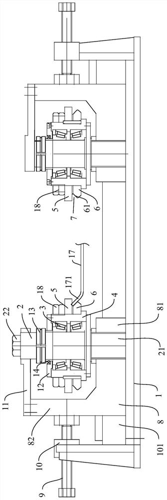
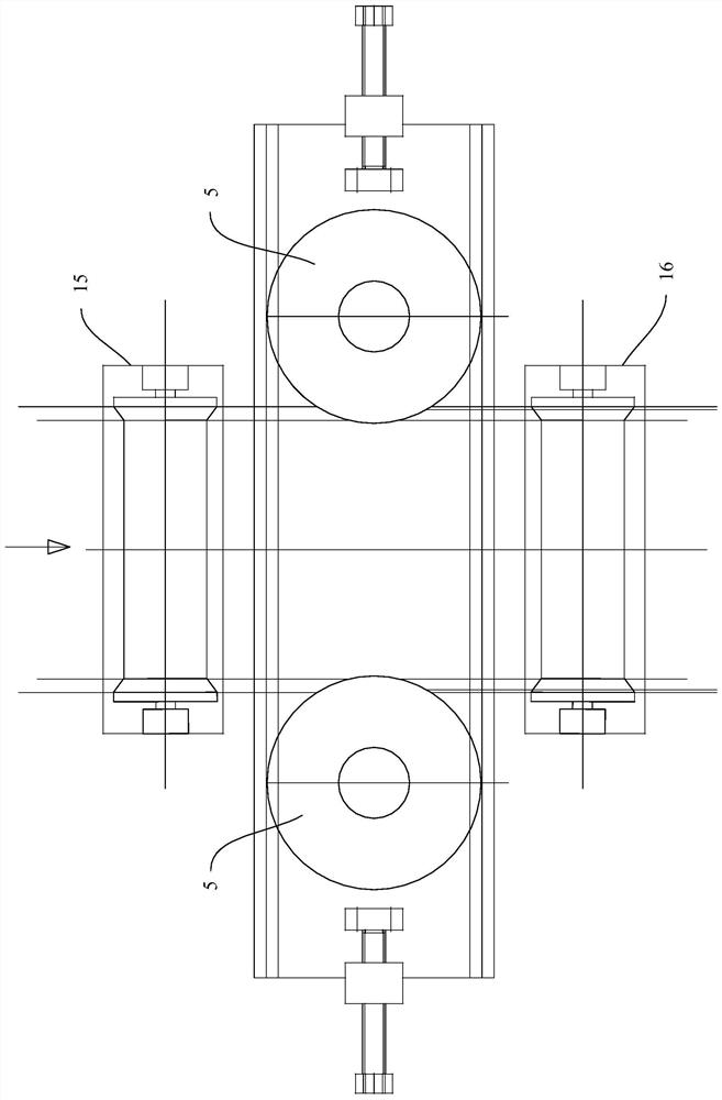
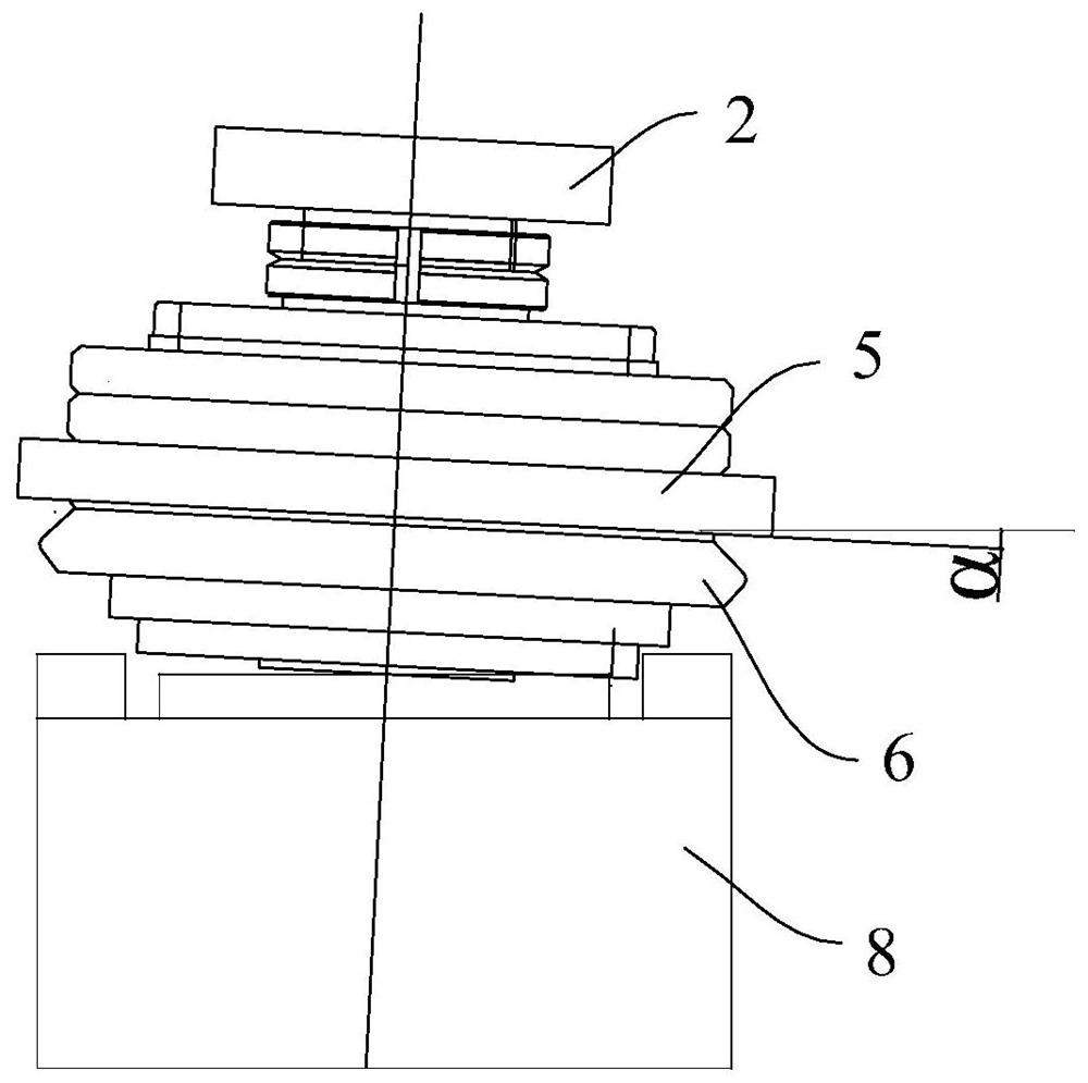
The invention provides a steel belt hobbing beveling machine which comprises a machine base and two sets of hobbing mechanisms installed on the machine base and arranged in a bilateral symmetry mode in the width direction of a steel belt. Each group of hobbing mechanism comprises a main shaft which extends up and down along the thickness direction of the steel belt, a bearing sleeve which is rotatably mounted on the periphery of the main shaft through a bearing, and scissors and a guide carrier roller which are fixed on the periphery of the bearing sleeve, the scissors and the guide carrier roller are disc-shaped and are arranged up and down, a guide part is arranged at the outer edge of the guide carrier roller, and the guide part is fixed on the bearing sleeve. The guide part obliquely extends in the mode that the closer the guide part is to the scissors, the more inward the guide part is, and a rolling-cutting area for containing the edge of the steel belt is formed between the guide part and the scissors. By means of the device, the edge of the steel belt can be continuously rolled and cut, chamfered edges of the edge of the steel belt can be continuously machined, the rolling cutting speed can meet the requirement for the high-frequency welding speed, therefore, the high-frequency welding technology can be used for the extremely-thick-wall steel pipe and the corner welding square pipe, the quality and efficiency of welding seams are improved, and product development is facilitated.

Description

technical field [0001] The invention relates to the field of production of high-frequency welded pipes and cold-formed rectangular pipes, in particular to a steel strip rolling and beveling machine and a steel strip rolling and beveling process performed by using the steel strip rolling and beveling machine. Background technique [0002] When the high-frequency welded pipe production line and the cold-formed rectangular pipe production line produce extremely thick steel pipes or cold-formed high-frequency welded products with special cross-sections, it is necessary to perform continuous and precise chamfering at a certain angle on the two sides of the steel strip before forming and welding, so as to Guarantee the welding quality of the product. At present, there are only planing and milling processes in the existing technology; however, because the thickness of the steel strip is large and it is not easy to weld, it is necessary to chamfer; and the amount of feed and process...

Claims


Application Information

Patent Timeline
IPC IPC(8): B23P23/04B23D31/00B23D33/02
CPCB23P23/04B23D31/00B23D33/02
Inventor 姜春民朱延波杨福君高志武杨慧莲李彬
Owner 湖南宝顺联冷弯科技有限公司
Learn More