Double-side inclined side hanging type lifting appliance and hoisting equipment with lifting appliance
A lifting equipment and side tilting technology, which is applied in the field of double-sided tilting side-mounted spreaders, can solve the problems of uncompact structure, insensitive movement, and large force on the lock head, so as to improve work efficiency and adaptability to working conditions , Improving the unloading rate of materials and preventing the lock from being stressed
- Summary
- Abstract
- Description
- Claims
- Application Information
AI Technical Summary
Problems solved by technology
Method used
Image

Examples
Embodiment approach
[0041] According to a first embodiment of the present invention, there is provided a double-sided inclined side-mounted spreader:
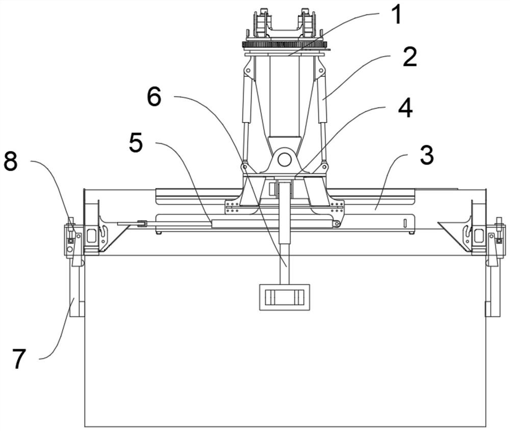
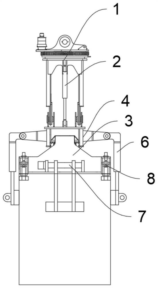
[0042] A double-sided inclined side-hanging spreader, the spreader includes: a turntable assembly 1 whose upper end is used to connect with lifting equipment; a bracket assembly 4 whose upper end is hinged to the lower end of the turntable assembly 1; The crossbeam assembly 3 in the bracket assembly 4, the crossbeam assembly 3 can move relative to the bracket assembly 4, the crossbeam assembly 3 is used to connect with the container; The tipping mechanism 2 on both sides of the hinge between the lower end of the lower end and the bracket assembly 4, the tipping mechanism 2 is used to control the rotation of the bracket assembly 4 relative to the turntable assembly 1; one end is connected to the beam The assembly 3 is connected, and the other end is connected with the side shift mechanism 5 of the bracket assembly 4, and the side shift mechanism 5 ...
Embodiment 1
[0071] A double-sided inclined side-hanging spreader, the spreader includes: a turntable assembly 1 whose upper end is used to connect with lifting equipment; a bracket assembly 4 whose upper end is hinged to the lower end of the turntable assembly 1; The crossbeam assembly 3 in the bracket assembly 4, the crossbeam assembly 3 can move relative to the bracket assembly 4, the crossbeam assembly 3 is used to connect with the container; The tipping mechanism 2 on both sides of the hinge between the lower end of the lower end and the bracket assembly 4, the tipping mechanism 2 is used to control the rotation of the bracket assembly 4 relative to the turntable assembly 1; one end is connected to the beam The assembly 3 is connected, and the other end is connected with the side shift mechanism 5 of the bracket assembly 4, and the side shift mechanism 5 is used to control and adjust the relative position of the beam assembly 3 and the bracket assembly 4, The lateral movement mechanis...
Embodiment 2
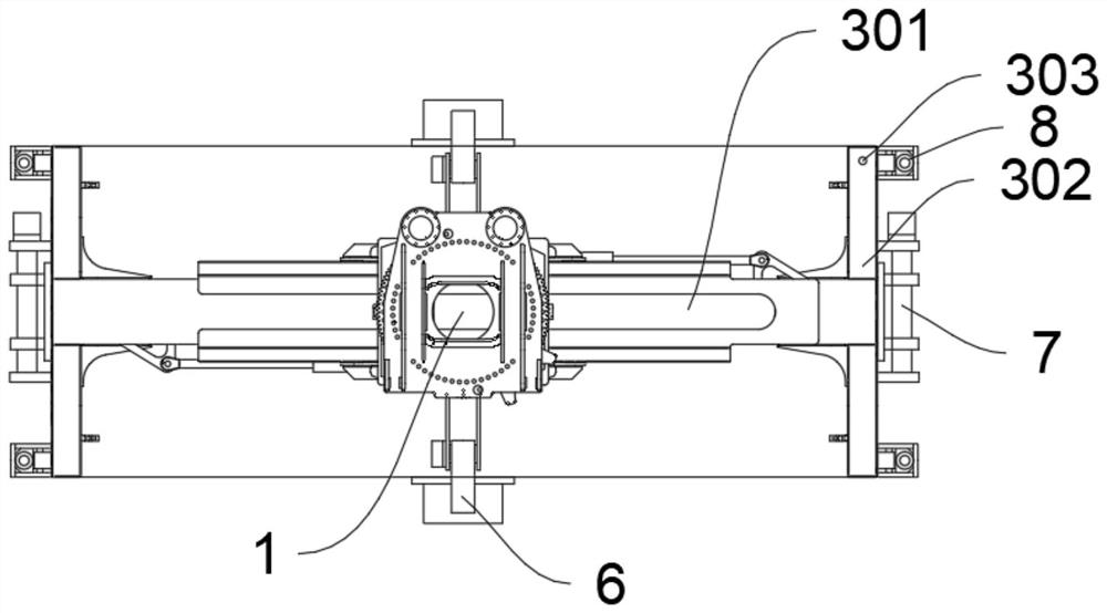
[0073] Example 1 is repeated, except that the bracket assembly 4 includes: a bracket body 401 hinged to the lower end of the turntable assembly 1 , and a first hinge for being hinged to the dumping mechanism 2 is provided on the bracket body 401 . Hinged support 405, the first articulated support 405 is located on both sides of the load-bearing hinge axis CZ1; the first leg group 402 connected to the bracket body 401 at the upper end, the first leg group 402 Located on one side of the load-bearing hinge axis CZ1, the legs of the first leg group 402 are separately arranged on both sides of the beam assembly 3; the upper end of the second leg group 403 connected to the bracket body 401 , the second outrigger group 403 is located on the other side of the load-bearing hinge axis CZ1, and the outriggers of the second outrigger group 403 are separately arranged on both sides of the beam assembly 3; The lower end of the outrigger set 402 and the lower end of the second outrigger set ...
PUM
 Abstract
Description
Claims
Application Information
 - R&D
- Intellectual Property
- Life Sciences
- Materials
- Tech Scout
- Unparalleled Data Quality
- Higher Quality Content
- 60% Fewer Hallucinations
Browse by: Latest US Patents, China's latest patents, Technical Efficacy Thesaurus, Application Domain, Technology Topic, Popular Technical Reports.
© 2025 PatSnap. All rights reserved.Legal|Privacy policy|Modern Slavery Act Transparency Statement|Sitemap|About US| Contact US: help@patsnap.com