
Optical lens support for coating machine

A technology of optical lens and coating machine, which is applied in the direction of optics, optical elements, sputtering coating, etc., can solve the problems of uneven coating and short service life, and achieve convenient loading and unloading, long service life and avoid wear and tear Effect

Pending Publication Date: 2022-03-08
HUBEI YANGTZE PHOTOELECTRIC INSTR CO LTD
View PDF10 Cites 0 Cited by
  • Summary
  • Abstract
  • Description
  • Claims
  • Application Information

AI Technical Summary

Problems solved by technology

[0005] Aiming at the deficiencies in the prior art, the present invention provides an optical lens holder for a coating machine, which solves the problems of uneven coating and short service life of the clamping structure of the optical lens existing in the prior art

Method used


Image

  • Optical lens support for coating machine
  • Optical lens support for coating machine
  • Optical lens support for coating machine

Examples


Embodiment Construction

[0021] The technical solutions in the present invention will be further described below in conjunction with the accompanying drawings and embodiments.

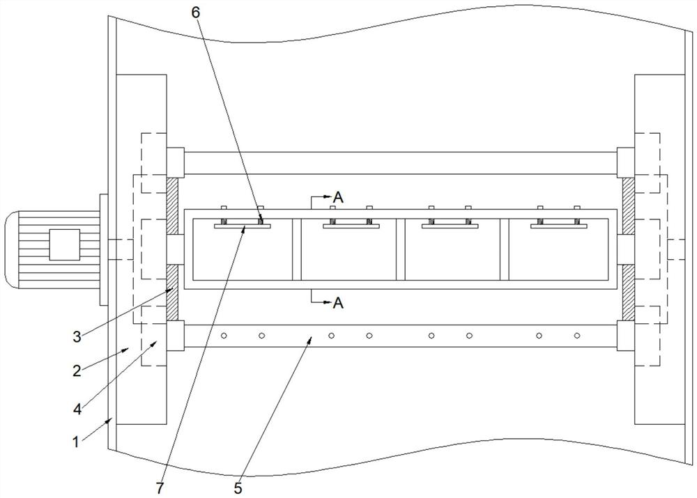
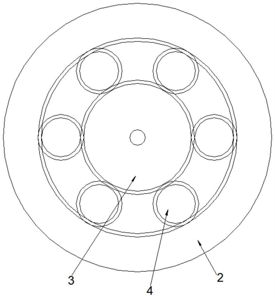
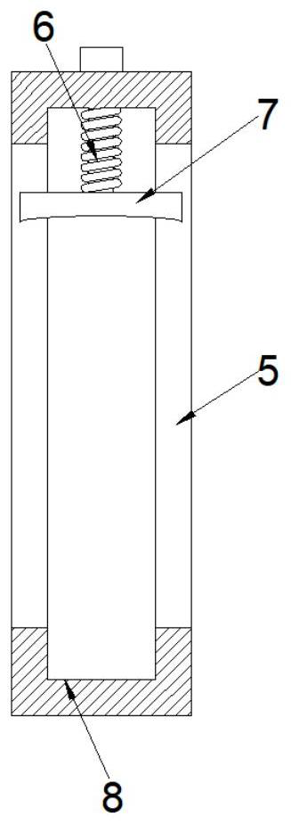
[0022] like figure 1 , figure 2 and Figure 4 As shown, in order to achieve uniform coating on both sides of the optical lens, the embodiment of the present invention proposes an optical lens holder for a coating machine, including a planetary gear assembly rotatably mounted on the inner wall of the housing 1, and the planetary gear 4 in the planetary gear assembly A connecting piece 5 is fixedly connected, and a mounting frame 9 for fixing the optical lens is detachably installed in the connecting piece 5. A circular fixing frame 10 is arranged in the mounting frame 9, and a circular fixing frame 10 is arranged in the fixing frame 10 along the axis mirror symmetrically toward the axis. The arc-shaped sheet 11 is convex in the direction, and the distance from the middle of the arc-shaped sheet 11 to the axis of the fixed fr...


PUM

PropertyMeasurementUnit
transmittivityaaaaaaaaaa

Abstract

The invention provides an optical lens support for a coating machine, which comprises a planet wheel assembly rotatably mounted on the inner wall of a shell, a connecting piece is fixedly connected to a planet gear in the planet wheel assembly, a mounting frame used for fixing an optical lens is detachably mounted in the connecting piece, a circular fixing frame is arranged in the mounting frame, and the fixing frame is fixedly connected with the planet wheel assembly. Arc-shaped pieces protruding towards the axis direction are arranged in the fixing frame in a mirror symmetry mode along the axis, and the distance between the middles of the arc-shaped pieces and the axis of the fixing frame is smaller than the radius of the light lens. The problems that in the prior art, coating is not uniform, and the service life of a clamping structure of the optical lens is short are solved, and the effects that the coating quality is improved, the dismounting and mounting efficiency of the optical lens is improved, and the service life of the clamping structure of the optical lens is prolonged are achieved.

Description

technical field [0001] The invention relates to the technical field of optical lens production equipment, in particular to an optical lens bracket for a coating machine. Background technique [0002] During the use of the lens, the reflection will reduce the transmittance of the light, which will cause interference and affect the quality of the image. The existing optical lens can effectively reduce the color reflection rate of the lens through the coating, so that the light transmittance of the lens can be increased to 98%. [0003] The structure of a common coating machine is to rotate and install a working turntable on the top of the housing with a cavity, install a mounting plate for loading lenses on the working turntable, and clamp the edge of the lens through the end of a rod pushed by a spring. A heating device is installed on the inner bottom of the shell, and the coating material is placed in the heating device. A guide plate that can adjust the gasification gas o...

Claims


Application Information

Patent Timeline
Patent Type & Authority Applications(China)
IPC IPC(8): C23C14/50C23C14/24G02B1/10
CPCC23C14/505C23C14/24G02B1/10
Inventor 何文华黄平张敏
Owner HUBEI YANGTZE PHOTOELECTRIC INSTR CO LTD
Features
  • Generate Ideas
  • Intellectual Property
  • Life Sciences
  • Materials
  • Tech Scout
  • Unparalleled Data Quality
  • Higher Quality Content
  • 60% Fewer Hallucinations
Learn More