Bearing with wear-resistant protection function and using method thereof

A technology of bearings and protective covers, which is applied in the direction of rotating bearings, bearings, ball bearings, etc., can solve the problems of reducing the service life of the device, not having a wear-resistant protection structure, and bearing wear, so as to avoid oil leakage and ensure service life , to ensure the effect of stability

Active Publication Date: 2022-03-08
HAIAN HENGYI SLIDING BEARING
View PDF9 Cites 0 Cited by
  • Summary
  • Abstract
  • Description
  • Claims
  • Application Information

AI Technical Summary

Problems solved by technology

", the device does not have a wear-resistant protection structure. When the bearing is connected with external components, due to the influence of the transmission force, the bearing will be worn and the service life of the device will be reduced.

Method used


Image

  • Bearing with wear-resistant protection function and using method thereof
  • Bearing with wear-resistant protection function and using method thereof
  • Bearing with wear-resistant protection function and using method thereof

Examples


Embodiment 1

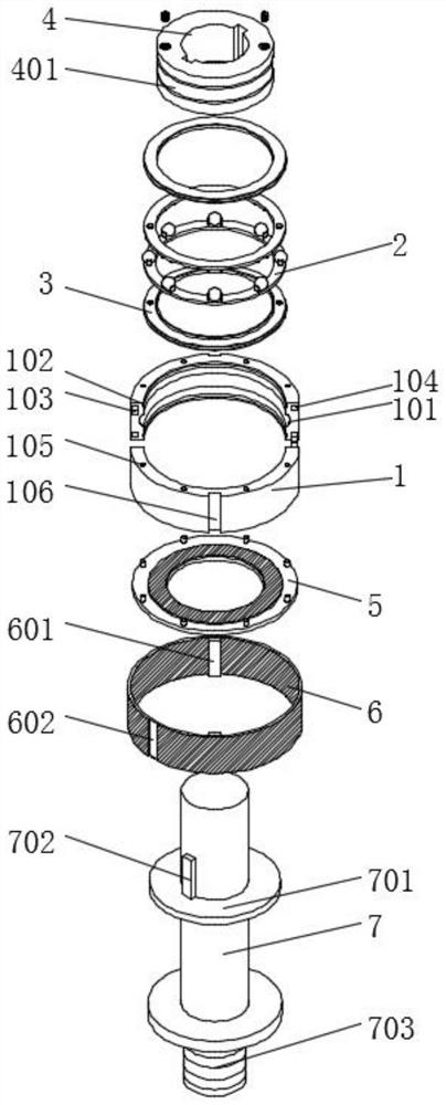
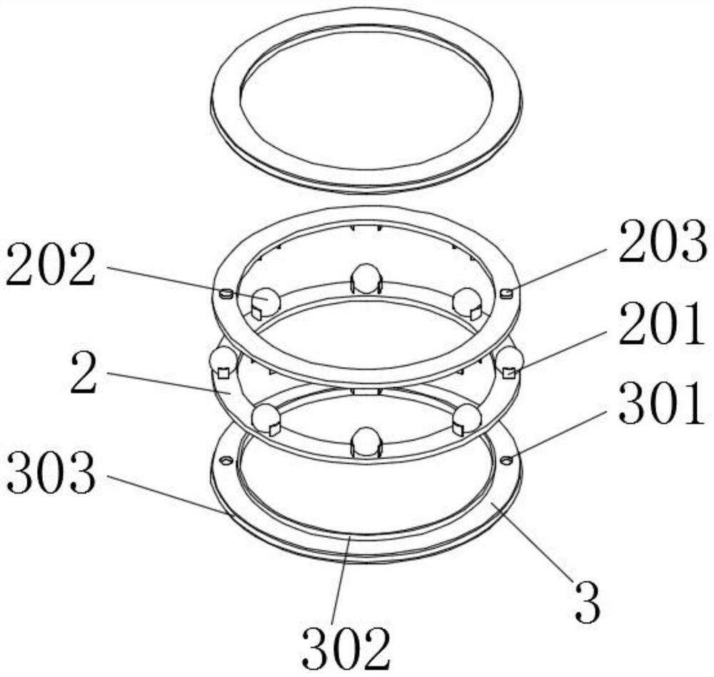
[0043] Embodiment 1 includes an outer assembly ring 1, a support ring 2 and a closure cover 3. The inner side of the outer assembly ring 1 is provided with two sets of fitting grooves 102 arranged up and down, and the inner sides of the two sets of fitting grooves 102 are fitted Fitting ring 303 is installed, and the inner side of two groups of said fitting rings 303 is equipped with closed cover 3, and the inner side of described closed cover 3 is installed with closed collar 302, and closed collar 302 is set on the outside of inner ring 4, two The opposite surfaces of the closed cover 3 of the group are all provided with symmetrically distributed limiting grooves 301, two groups of support rings 2 are installed on the opposite surfaces of the closed cover 3, and positioning blocks 203 are installed on the outside of the two groups of support rings 2, and the positioning blocks 203 Fitted and installed on the inner side of the limit groove 301, the opposite surfaces of the two...

Embodiment 2

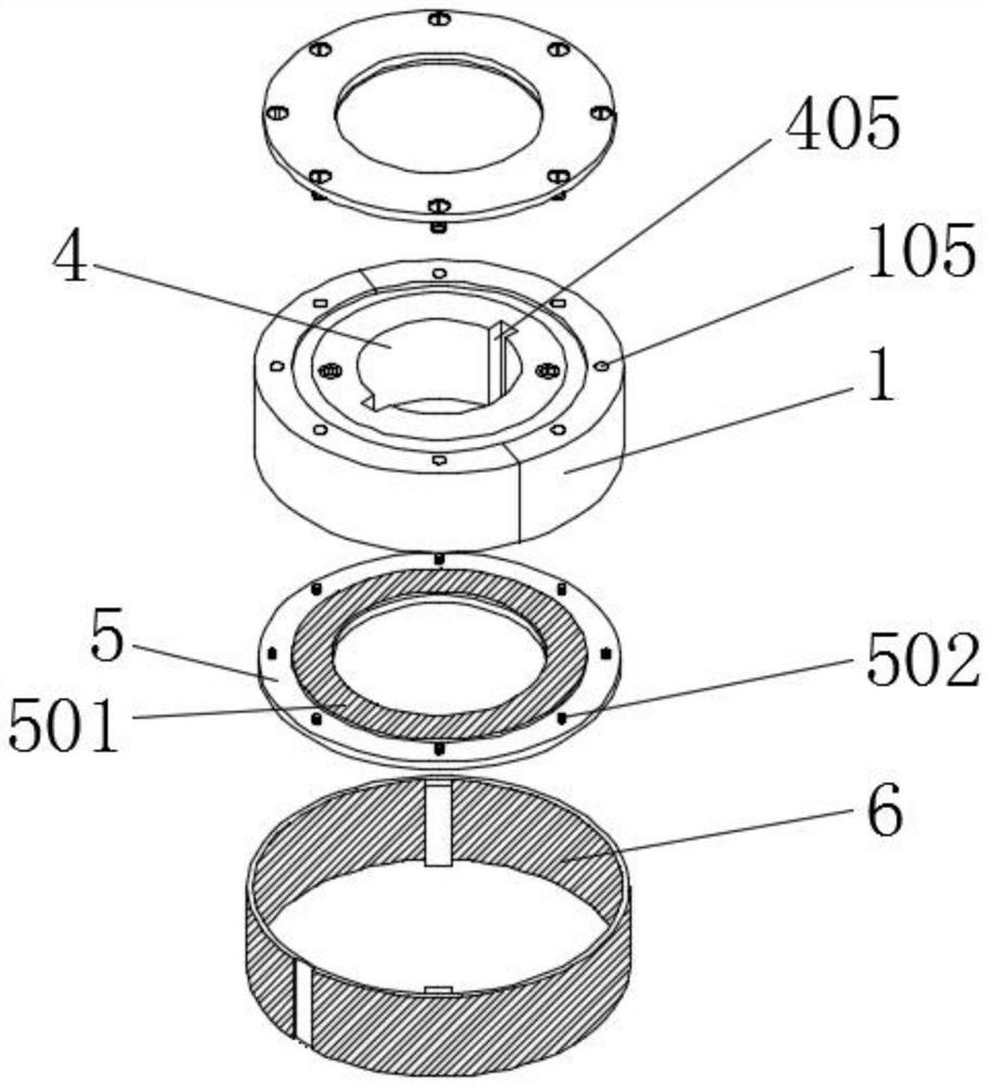
[0045] Embodiment 2 includes an outer assembly ring 1, a support ring 2 and a closure cover 3. An inner ring 4 is installed on the inner side of the anti-friction guide groove 401, and a threaded oil injection hole 402 is opened on the top of the inner ring 4. The threaded The inner side of the oil injection hole 402 is threaded with a threaded closing plug 404, and the bottom of the threaded oil injection hole 402 is equipped with an oil guide tube 403, which is installed inside the inner ring 4, and one end of the oil guide tube 403 runs through the anti-friction guide groove 401 The worker aligns the oil injection structure with the threaded oil injection hole 402 to drive the inner side, injects the lubricant into the inside of the oil guide pipe 403 through the thread oil injection hole 402, and the oil guide tube 403 transmits the lubricant to the anti-friction guide groove 401, and the lubrication The lubricant is injected into the inside of the bearing device, and the f...

Embodiment 3

[0047] The third embodiment includes the outer assembly ring 1, the outer side of the outer assembly ring 1 is covered with a rubber ring 6, the inner side of the rubber ring 6 is installed with a positioning piece 601, and the positioning piece 601 is fitted in the inner side of the positioning groove 106, so that The outside of the rubber ring 6 is provided with a card slot 602. The user fits the positioning piece 601 on the rubber ring 6 inside the positioning groove 106, and the outer assembly ring 1 positions the outer rubber ring 6 through the positioning groove 106 to ensure that the rubber ring 6 The stability of the ring 6, the rubber ring 6 is fit and connected with the external structure through the slot 602, and the friction force of the rubber ring 6 and the positioning of the slot 602 ensure the normal use of the transmission on the device.

[0048] see figure 1 , an embodiment provided by the present invention: a bearing with wear protection and its use method; ...


PUM


Abstract

The bearing comprises an outer assembling ring, a supporting ring and a sealing cover, two sets of vertically-arranged embedding grooves are formed in the inner side of the outer assembling ring, embedding rings are installed on the inner sides of the two sets of embedding grooves in an embedded mode, and the sealing cover is installed on the inner sides of the two sets of embedding rings. Limiting grooves which are symmetrically distributed are formed in the opposite faces of the two sets of sealing covers, two sets of supporting rings are installed on the opposite faces of the sealing covers, positioning blocks are installed on the outer sides of the two sets of supporting rings, and the positioning blocks are installed on the inner sides of the limiting grooves in an embedded mode. The rubber ring is installed, the positioning piece on the rubber ring is embedded into the inner side of the positioning groove, the outer assembling ring positions the rubber ring on the outer side through the positioning groove, the stability of the rubber ring is guaranteed, the rubber ring is connected with an external structure in an embedded mode through the clamping groove, and the stability of the rubber ring is guaranteed through friction force of the rubber ring and positioning of the clamping groove. Normal use of transmission on the device is guaranteed, friction force of the device is increased through a rubber ring, and safety of the device is guaranteed.

Description

technical field [0001] The invention relates to the technical field of bearings, in particular to a bearing with wear protection and a use method thereof. Background technique [0002] A bearing is a mechanical element that limits relative motion within the required range of motion and reduces friction between moving parts, and ensures its rotation accuracy. Sliding bearings have no inner and outer rings and no rolling bodies, and are generally made of wear-resistant materials. It is a very important part in the transmission structure. [0003] The defective that bearing exists in the prior art is: [0004] 1. The patent document CN214998819U discloses a bearing that is easy to assemble, "including a bearing assembly assembly and a bearing positioning assembly. The bearing assembly assembly includes a bearing outer ring, a cage, and a bearing inner ring. The bearing outer ring includes an outer Ring I, outer ring II and insert tongues, two insert tongues are provided, and ...

Claims


Application Information

Patent Timeline
Patent Type & Authority Applications(China)
IPC IPC(8): F16C19/52F16C19/02F16C33/58F16C33/60F16C33/66F16C33/78F16C35/073
CPCF16C19/52F16C19/02F16C33/583F16C33/585F16C33/60F16C33/6659F16C33/7806F16C33/7816F16C35/073
Inventor 卢稳舟雷蔚川卢镔
Owner HAIAN HENGYI SLIDING BEARING
Why Eureka
Try Eureka