
Frequency reconfigurable filtering antenna design method

A technology for reconstructing filtering and design methods, applied in antennas, design optimization/simulation, antenna grounding switch structure connection, etc., can solve the problems of antenna gain reduction, violation of antenna simplicity and miniaturization, etc. The effect of obvious suppression ability and high in-band gain

Pending Publication Date: 2022-03-08
ANHUI UNIVERSITY +1
View PDF0 Cites 0 Cited by
  • Summary
  • Abstract
  • Description
  • Claims
  • Application Information

AI Technical Summary

Problems solved by technology

[0003] Most of the current frequency reconfigurable filter antennas are a combination of frequency-variable bandpass filters and broadband antennas. This structure has two disadvantages: the first disadvantage is that frequency-variable bandpass filters are often composed of PIN diodes Composed of varactor diodes, these devices require an external bias circuit, which violates the trend of antenna simplification and miniaturization; the second disadvantage is that the antenna gain is reduced, because the filter is lossy, and the gain is An important parameter of the filter antenna

Method used


Image

  • Frequency reconfigurable filtering antenna design method
  • Frequency reconfigurable filtering antenna design method
  • Frequency reconfigurable filtering antenna design method

Examples


Embodiment Construction

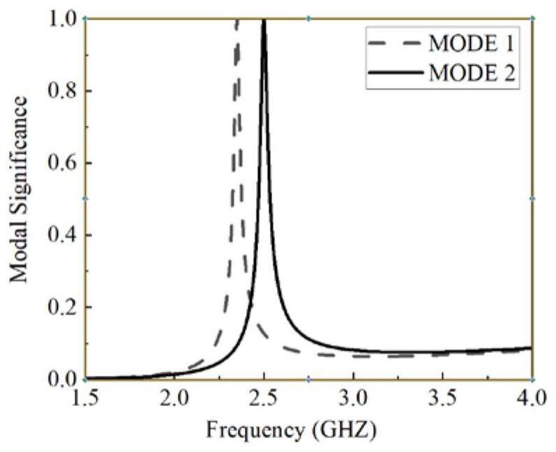
[0061]A frequency reconfigurable filter antenna design method, the method comprises the steps of the following sequence:

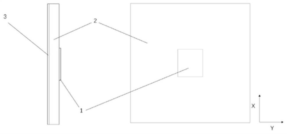
[0062] (1) set up the microstrip filter antenna model, carry out pattern analysis to the microstrip filter antenna, draw the mode curve characteristic of the microstrip filter antenna; Described microstrip filter antenna model is made up of rectangular radiation patch 1, first dielectric plate 2 and Composed of metal floor 3, the model of the first dielectric board 2 is FR-4, the rectangular radiation patch 1 is printed on the upper surface of the first dielectric board 2, and the metal floor 3 is printed on the lower surface of the first dielectric board 2;

[0063] (2) setting the parasitic patch 4 on the microstrip filter antenna;

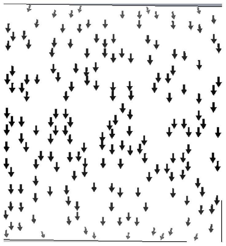
[0064] (3) Carry out eigenmode analysis to the microstrip filter antenna with parasitic patch 4, analyze all patterns, modify the structure of the antenna according to its pattern current for the pattern that does not meet t...


PUM


Abstract

The invention relates to a frequency reconfigurable filtering antenna design method, which comprises the following steps of: establishing a microstrip filtering antenna model, and performing mode analysis on a microstrip filtering antenna to obtain mode curve characteristics of the microstrip filtering antenna; a parasitic patch is arranged on the microstrip filtering antenna; carrying out characteristic mode analysis on the microstrip filtering antenna with the parasitic patch, analyzing all modes, and modifying the structure of the antenna according to the mode current of the mode which does not accord with the microstrip filtering antenna; and analyzing distribution characteristics of current in all modes, adding an excitation structure, and finally performing simulation optimization on the antenna structure. According to the invention, the characteristic mode theory is used to realize the display of the potential radiation capability of the radiator in any frequency domain range, so that the needed mode can be found and utilized conveniently, and the influence of the unneeded mode can be changed according to the mode current; according to the method, the selection of antenna feed is guided by using the characteristic mode theory, and the workload in the antenna design process is reduced.

Description

technical field [0001] The invention relates to the technical field of antenna design, in particular to a frequency reconfigurable filter antenna design method. Background technique [0002] With the rapid development of wireless communications, spectrum resources are increasingly scarce, and frequency bands are becoming more and more crowded. However, people realize that the current spectrum usage methods do not fully utilize the existing spectrum resources. Knowing radio is a more recognized way to make full use of spectrum resources. It is through autonomous learning and perception of corresponding frequency bands, and can allocate the communication frequency bands to be carried out to unoccupied frequency bands. At the same time, due to the increasing integration of modern antennas, the mutual interference between frequency bands has become more and more serious. Filter antennas have attracted the attention and research of many scholars due to their good out-of-band supp...

Claims


Application Information

Patent Timeline
Patent Type & Authority Applications(China)
IPC IPC(8): G06F30/10G06F30/20H01Q1/50H01Q15/00
CPCG06F30/10G06F30/20H01Q15/002H01Q1/50
Inventor 程光尚楚佰通黄志祥杨利霞刘银燕
Owner ANHUI UNIVERSITY
Learn More