Wiring method and device of programmable device, electronic equipment and storage medium

A wiring method and device technology, applied in the fields of instruments, electrical digital data processing, computer-aided design, etc., can solve the problems of poor wiring operation flexibility, poor user experience, and slow wiring speed, so as to improve the use experience and enhance the use experience. , the effect of short wiring time

Pending Publication Date: 2022-03-08
SHENZHEN PANGO MICROSYST CO LTD
View PDF0 Cites 0 Cited by
  • Summary
  • Abstract
  • Description
  • Claims
  • Application Information

AI Technical Summary

Problems solved by technology

[0004] Most of the existing programmable devices do not distinguish between ordinary fan-out user-designed circuit connections and high-fan-out user-designed circuit connections when selecting a suitable intermediate node. This programmable device uses only PathFinder and A* extended routing algorithm flow to obtain intermediate nodes, this kind of routing algorithm flow based only on PathFinder and A* extended routing speed is slow when routing high fan-out user-designed circuit connections, and the routing time Long, poor user experience
[0005] When selecting a suitable intermediate node, a small number of existing programmable devices distinguish between ordinary user-designed circuit connections and high-fan-out user-designed circuit connections, but this programmable device uses a pre-wiring method to Obtaining intermediate nodes is equivalent to directly specifying certain routing nodes as intermediate nodes in the high fan-out user-designed circuit connections before executing the routing algorithm process on the high-fan-out user-designed circuit connections, and different routing The end points are assigned to different new routing starting points. This method of obtaining intermediate nodes through pre-routing is equivalent to allocating routing paths in advance, which will make subsequent routing operations less flexible and slower. Long wiring time and poor user experience

Method used


Image

  • Wiring method and device of programmable device, electronic equipment and storage medium
  • Wiring method and device of programmable device, electronic equipment and storage medium
  • Wiring method and device of programmable device, electronic equipment and storage medium

Examples


Embodiment Construction

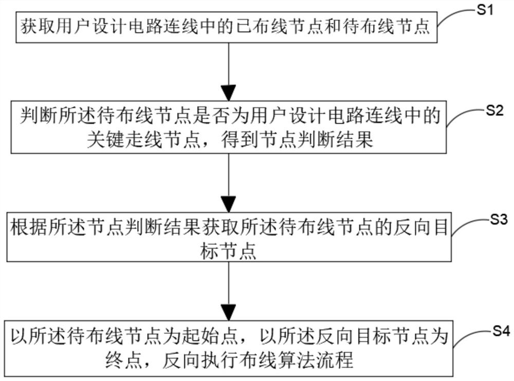
[0028] The following will clearly and completely describe the technical solutions in the embodiments of the present invention with reference to the accompanying drawings in the embodiments of the present invention. Obviously, the described embodiments are only some, not all, embodiments of the present invention. Based on the embodiments of the present invention, all other embodiments obtained by persons of ordinary skill in the art without making creative efforts belong to the protection scope of the present invention.

[0029] The terms "first", "second", and "third" in the present invention are only used for descriptive purposes, and cannot be understood as indicating or implying relative importance or implicitly specifying the quantity of indicated technical features. Thus, a feature defined as "first", "second", and "third" may explicitly or implicitly include at least one of such features. In the description of the present invention, "plurality" means at least two, such a...


PUM


Abstract

The invention discloses a wiring method and device of a programmable device, electronic equipment and a storage medium, and belongs to the field of integrated circuit design. The method comprises the following steps: acquiring wired nodes and to-be-wired nodes in a circuit connection line designed by a user; judging whether the to-be-wired node is a key wiring node in a user design circuit connection line or not, and obtaining a node judgment result; obtaining a reverse target node of the to-be-wired node according to the node judgment result, wherein the reverse target node comprises a wiring starting point of the user design circuit connection line and a wired node near the to-be-wired node; and reversely executing a wiring algorithm flow by taking the node to be wired as a starting point and the reverse target node as an end point. According to the invention, the wiring path does not need to be allocated in advance, so that the subsequent wiring operation is relatively flexible, the wiring speed is relatively high, the wiring time is relatively short, and the user experience is relatively good.

Description

technical field [0001] The invention belongs to the field of integrated circuit design, relates to field programmable logic device (referred to as programmable device) integrated circuit software tool design technology, in particular to a wiring method, device, electronic equipment and storage medium for programmable devices. Background technique [0002] In the routing module of ultra-large-scale programmable devices, the user-designed circuit connections with high fan-out usually refer to those user-designed connection lines with only one routing start point (source) and m routing end points (sink), and the routing end point ( The number m of sinks) is usually large (more than 1000). [0003] When it is necessary to execute the routing algorithm flow for the high fan-out user-designed circuit connection in the ultra-large-scale programmable device, the routing operation is from the routing start point (source) to the routing end point (sink), and a new routing end point W...

Claims


Application Information

Patent Timeline
Patent Type & Authority Applications(China)
IPC IPC(8): G06F30/394
CPCG06F30/394
Inventor 冯展鹏张鑫夏炜
Owner SHENZHEN PANGO MICROSYST CO LTD
Why Eureka
Try Eureka