
Crank machining system and machining method

A processing system and crank technology, applied in metal processing equipment, metal processing machinery parts, manufacturing tools, etc., can solve the problems of slow grinding crankshaft speed and single processing procedure, achieve fast grinding speed, improve production efficiency and processing accuracy, Solve the effect of a single processing procedure

Active Publication Date: 2022-03-11
青岛迈特园林机械零部件有限公司
View PDF5 Cites 0 Cited by
  • Summary
  • Abstract
  • Description
  • Claims
  • Application Information

AI Technical Summary

Problems solved by technology

[0003] The present invention aims to solve the above problems, and provides a crank processing system and processing method, which solves the problem that the grinding speed of the crankshaft of the existing equipment is relatively slow, and solves the problem of the single processing procedure of the existing equipment

Method used


Image

  • Crank machining system and machining method
  • Crank machining system and machining method
  • Crank machining system and machining method

Examples


Embodiment 1

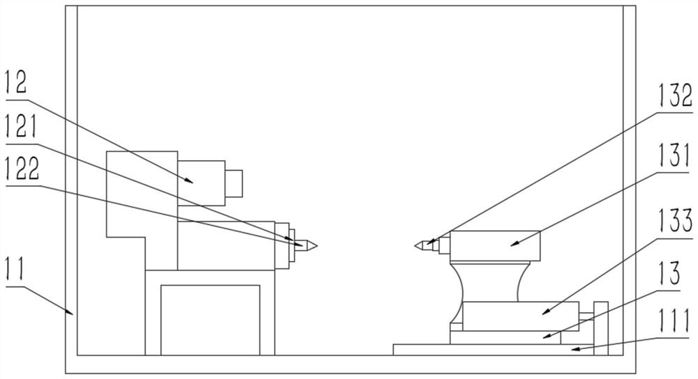
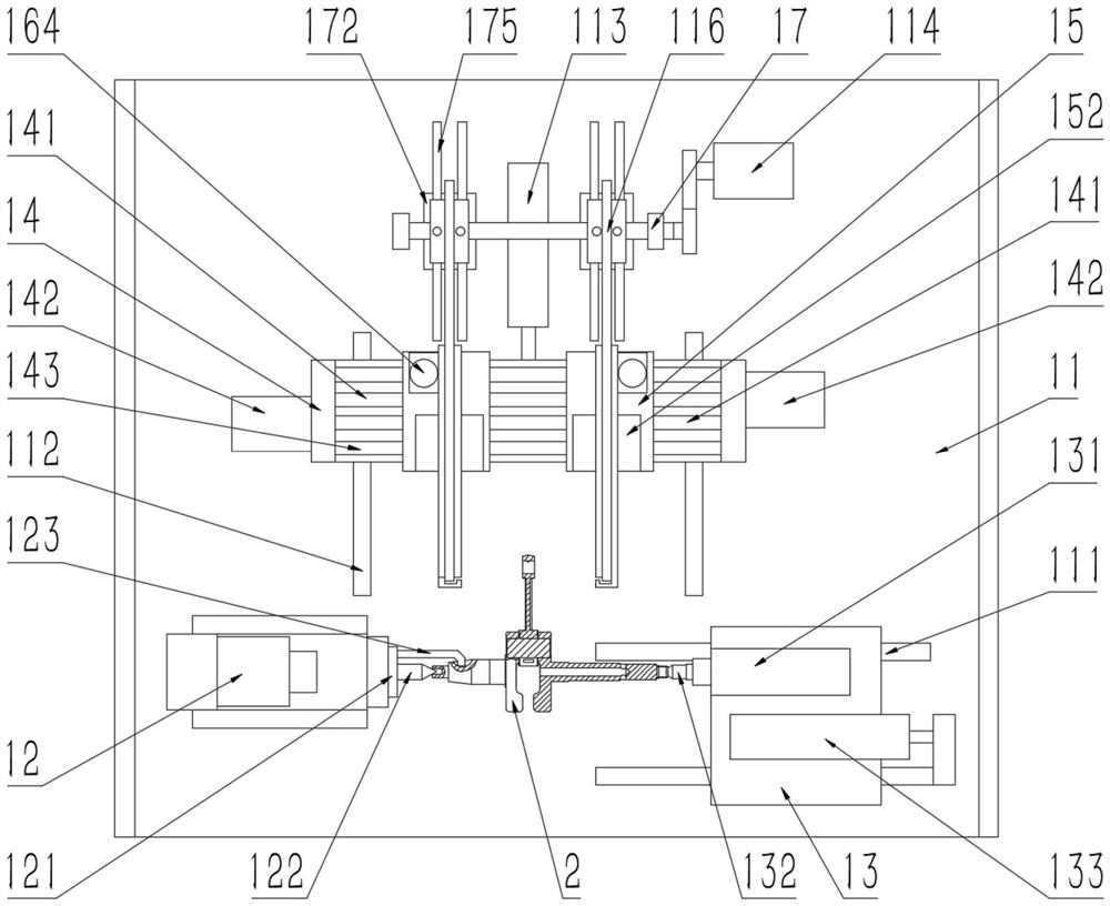
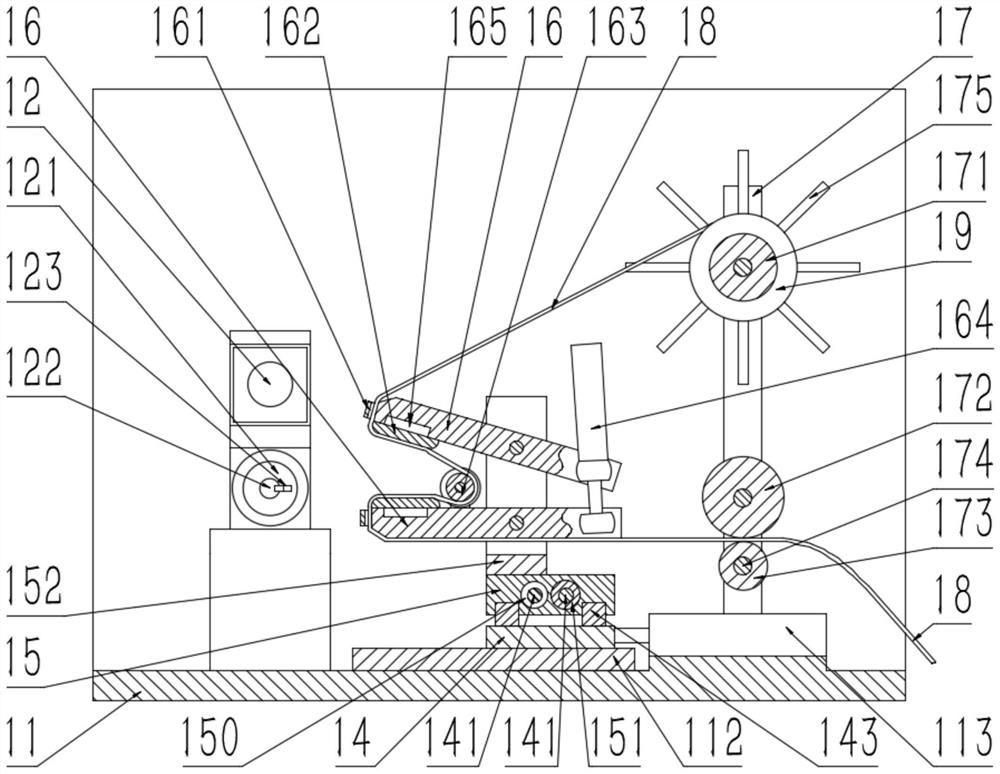
[0059] Such as Figure 1 to Figure 17 As shown, the present embodiment provides a crank processing system, including: a crank grinding device, a drilling device, a roughing device and a finishing device, the drilling device is used to drill holes at the front end and the rear end of the crank 21, The rough machining device is used for rough machining the crank 21 , the finish machining device is used for finishing the crank 21 , and the crank grinding device is used for grinding the crank 21 .

[0060] Further, the drilling device includes a second frame 31, a first driving device 32, a second spindle head 33, a first drill 331, a fixed plate 34, a support column 341, a fourth cylinder 35, a rotary cylinder 36, Pressing plate 361, the fifth cylinder 37, the first connecting rod 38, the concave pressing plate 381 and the second connecting rod 39, the top of the second frame 31 is fixedly connected with the fixed plate 34, and the fixed plate 34 is formed with a first through H...


PUM


Abstract

The invention relates to a crank machining system and method. A drilling device is used for drilling the front end and the rear end of a crank, a rough machining device is used for rough machining of the crank, a finish machining device is used for finish machining of the crank, and a crank grinding device is used for grinding the crank. According to the crankshaft polishing device, two parts of a crankshaft are polished through the two sets of clamping plates correspondingly, meanwhile, each part is provided with two contact surfaces making contact with abrasive paper, the polishing speed is high, and the problem that the crankshaft polishing speed of existing equipment is low is solved; the drilling device can drill holes in the two ends respectively through one-time clamping, the rough machining device can finish drilling, chambering and rough machining of the end face through one-time clamping, the finish machining device can finish radius boring, fine boring and finish machining of the end face through one-time clamping, one-time clamping of one device corresponds to multiple working procedures, the number of times of transferring and clamping is reduced, the production efficiency and the machining precision are improved, and the production cost is reduced. The problem that an existing device is single in machining procedure is solved.

Description

technical field [0001] The invention relates to the field of crankshaft processing, in particular to a crank processing system and a processing method. Background technique [0002] Existing crankshaft all is that crankshaft does not move, and emery wheel rotates, is to polish crankshaft by emery wheel and crankshaft surface contact. This grinding method has only one rotating grinding wheel during grinding, and the grinding wheel has only one contact surface with the crankshaft, so the grinding speed is relatively slow. At the same time, the accuracy of grinding the conical surface is poor. Simultaneously each equipment in the crank production process can only carry out the processing of a kind of process, and the total number of transfers of the crank in the production process is many, causing the production efficiency of the crank to decline. Contents of the invention [0003] The present invention aims to solve the above problems, and provides a crank processing syste...

Claims


Application Information

Patent Timeline
Patent Type & Authority Applications(China)
IPC IPC(8): B23P15/00B23Q3/06B23Q11/00
CPCB23P15/00B23Q3/06B23Q11/00
Inventor 纪玉良查新刚
Owner 青岛迈特园林机械零部件有限公司
Learn More