Cooling energy-saving device for cooling tower and wet cooling tower

An energy-saving device and cooling tower technology, applied in water shower coolers, lighting and heating equipment, direct contact heat exchangers, etc., can solve problems such as the inability to lower the temperature of the tower water, economic losses, and high power consumption in cooling tower operation , to achieve the effect of saving circulating water supply power consumption, reducing cooling water temperature, and reducing cloud water loss

Active Publication Date: 2022-03-11
CHONGQING UNIV
View PDF8 Cites 0 Cited by
  • Summary
  • Abstract
  • Description
  • Claims
  • Application Information

AI Technical Summary

Problems solved by technology

In the wet cooling tower, the circulating water is in direct contact with the air, and the heat in the water is transferred to the air through contact heat transfer and evaporative heat dissipation. The cooling effect of the wet cooling tower is theoretically limited by the wet bulb temperature of the ambient air. The limit temperature for water to be cooled is The wet bulb temperature of the ambient air; in actual engineering, the existing wet cooling towers can usually only cool the circulating water to 3~5°C above the wet bulb temperature of the ambient air
At the same time, the loss of circulating water caused by evaporation in the wet cooling tower is an important part of the water loss of the cooling tower, and it is also the largest water consumption item of the coal-fired power unit. The water consumption of the cooling tower has caused great economic losses.
In addition, the reservoir is at the bottom of the cylinder, and the lifting height of the circulating water during the cooling process is relatively high, and the cooling tower consumes a lot of power
[0004] Due to the structure of the packing layer, the problems of the existing wet cooling towers are: the temperature of the water out of the tower cannot be lowered below the wet bulb temperature of the ambient air, the loss of cloud water is large and the power consumption of operation is high

Method used


Image

  • Cooling energy-saving device for cooling tower and wet cooling tower
  • Cooling energy-saving device for cooling tower and wet cooling tower
  • Cooling energy-saving device for cooling tower and wet cooling tower

Examples


Embodiment Construction

[0023] Below in conjunction with accompanying drawing and embodiment the present invention will be further described:

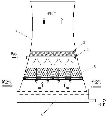
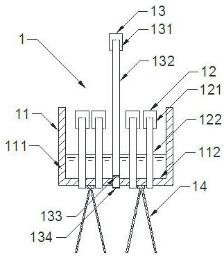
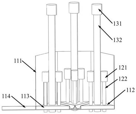
[0024] Such as figure 2 and image 3 As shown, a cooling and energy-saving device 1 for a cooling tower of the present invention includes a sump 11 and an air precooling device 12, the sump 11 closes the inner wall of the tower tube 1, and the air precooling device 12 passes through the bottom of the sump 11, and the air The lower inlet of the precooling device 12 communicates with the fresh air entering from the lower part of the tower 1, and the top outlet is provided with a wind cap 121 for shielding water droplets.

[0025] Such as figure 2 and Figure 7 As shown, the cooling and energy-saving device 1 is on the support frame 14, and the support frame 14 is supported from the ground on the bottom surface of the sump 11, which reduces the height of the water droplets in the rain area and saves the power consumption of the circulating water supply of t...


PUM


Abstract

The cooling energy-saving device comprises a water collecting tank and an air pre-cooling device, the water collecting tank seals the inner wall of a tower cylinder, and the air pre-cooling device penetrates through the bottom of the water collecting tank. An inlet in the lower part of the air pre-cooling device is communicated with fresh air entering from the lower part of the tower drum, and an air cap for shielding water drops is arranged at an outlet in the top of the air pre-cooling device. The wet cooling tower comprises a tower drum arranged on the ground; a cooling tower filler, a splashing device and a dehydrator are arranged in the tower barrel from bottom to top, an air inlet is formed in the bottom of the tower barrel, the cooling energy-saving device is further included, and a main body of the cooling energy-saving device is located between the air inlet and the cooling tower filler. The problems that the cooling limit of the wet cooling tower is limited by the environment wet bulb temperature, the cloud water loss is large, and the operation power consumption is high are effectively solved.

Description

technical field [0001] The invention relates to a wet cooling tower. Background technique [0002] Such as figure 1 As shown, the existing wet cooling tower mainly includes a cylinder 2, which is sequentially provided with a water reservoir 6, a cooling tower filler 5, a splash device 4 and a water eliminator 3 from bottom to top; some tops also have an exhaust fan. The periphery of cylinder body 2 is supported on the ground. Reservoir 6 is on the ground (the bottom is waterproofed), and cooling tower filler 5, splashing device 4 and water eliminator 3 are all installed on a concrete support, and the concrete support is supported on the reservoir ground. For coal power units in the power system, the role of the cooling tower is to reduce the temperature of the tower water to reduce the back pressure of the steam turbine and improve the working ability of the steam. [0003] Wet cooling towers are widely used in fields that require a large number of cold sources, such as e...

Claims


Application Information

Patent Timeline
Patent Type & Authority Applications(China)
IPC IPC(8): F28C1/14F28F25/00F28F25/02
CPCF28C1/14F28F25/00F28F25/02F28F2025/005
Inventor 卢啸风王济平范旭宸王泉海李建波亢银虎赵辰阳董中豪张戎迪
Owner CHONGQING UNIV
Why Eureka
Try Eureka