Refractive-diffractive projection illumination system

A lighting system and projection technology, applied in the field of optical projection, can solve the problems of inability to adapt to miniaturization requirements, large size of projection lighting devices, etc., and achieve the effects of meeting market demand, reducing volume, and shortening optical path.

Pending Publication Date: 2022-03-11
ONGINE TECH LTD
View PDF6 Cites 0 Cited by
  • Summary
  • Abstract
  • Description
  • Claims
  • Application Information

AI Technical Summary

Problems solved by technology

[0004] And in the existing projection system, such as the display device disclosed in Chinese Patent Publication No. CN101257637B and the projection type lighting device, include as the dimming part that makes the amount of light emitted from the light source variable, using a smaller size than the liquid crystal panel for image display , the light modulation unit composed of a liquid crystal panel that modulates the intensity of incident light corresponding to the video signal, and the light beam modulated by the light modulation unit for each pixel according to the video signal is amplified by the projection unit and projected on the liquid crystal for image display On the panel, the projection lighting device can improve the contrast of the image, but due to the limitation of the optical path, the size of the projection lighting device is too large, which cannot meet the miniaturization requirements of the current market

Method used


Image

  • Refractive-diffractive projection illumination system
  • Refractive-diffractive projection illumination system
  • Refractive-diffractive projection illumination system

Examples


Embodiment Construction

[0037] The technical solution of the present invention will be further described in detail below in conjunction with the accompanying drawings, but the protection scope of the present invention is not limited to the following description.

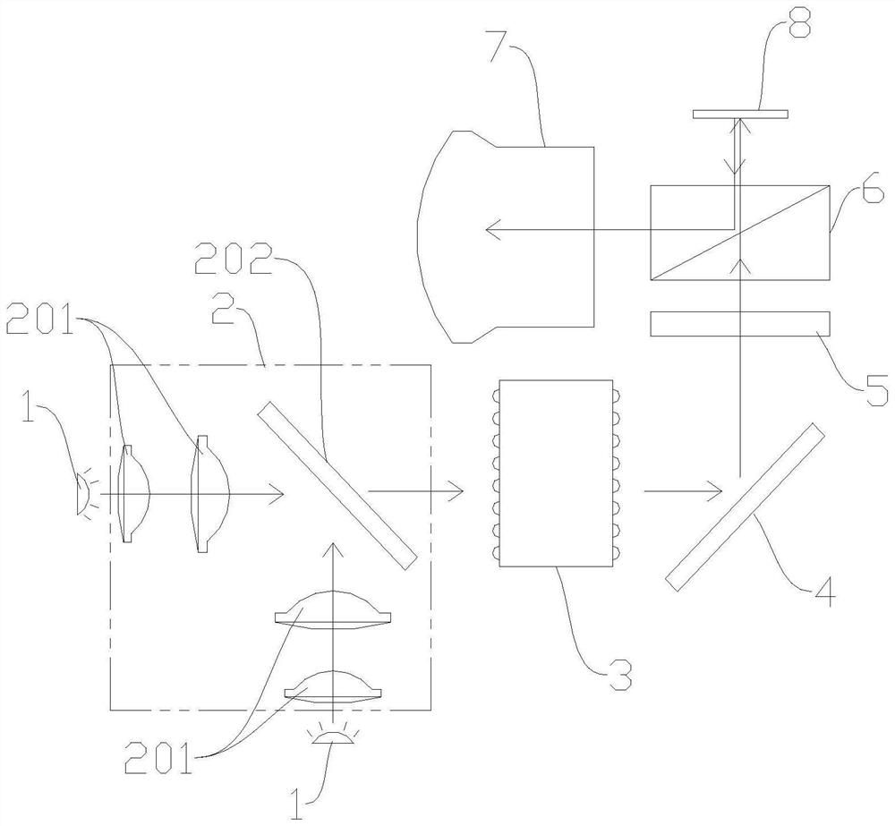
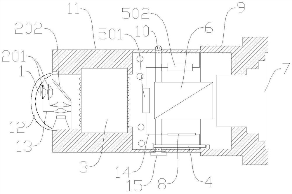
[0038] Such as Figure 1~6 As shown, a refraction-diffractive projection lighting system includes a light source module 1, a light receiving system 2, a light homogenizing device 3, a reflector 4, a diffractive optical element 5, a prism module 6 and a lens 7 arranged in sequence. The system 2 is used to collimate the light emitted by the light source module 1 and emit it onto the uniform light device 3, the two effective optical surfaces of the uniform light device 3 are respectively distributed with micro-lens arrays, and the two effective optical surfaces are The microlens arrays are symmetrical to each other. The light is incident on the reflector 4 after passing through the homogenizing device 3, and is incident on the diffractive opti...


PUM

PropertyMeasurementUnit
radiusaaaaaaaaaa

Abstract

The invention relates to the technical field of optical projection, in particular to a refractive-diffractive projection illumination system, which comprises a light source module, a light receiving system, a dodging device, a reflector, a diffractive optical element, a prism module and a lens which are sequentially arranged, and is characterized in that the light receiving system is used for collimating light rays emitted by the light source module and emitting the light rays to the dodging device; micro-lens arrays are distributed on two effective optical surfaces of the dodging device respectively, the micro-lens arrays on the two effective optical surfaces are symmetrical to each other, light enters the reflecting mirror after passing through the dodging device, enters the diffractive optical element after being reflected by the reflecting mirror, and exits the prism module after passing through the diffractive optical element. After the chip receives the light rays, image light rays are formed and emitted to the prism module, and the image light rays are emitted to the lens through the prism module. The diffractive optical element is arranged between the dodging device and the prism module, so that the optical path is effectively shortened, the size is reduced, and the miniaturized design of equipment is realized.

Description

technical field [0001] The invention relates to the technical field of optical projection, in particular to a refraction projection lighting system. Background technique [0002] With the rapid development and popularization of the Internet, the video display industry has also entered the Internet age from the digital age, and is developing towards networking, high-definition, and intelligent aspects. Because of this, the demand for electronic information products has also changed, and products such as tablet computers, smart phones, and smart wearables have gradually developed and matured under the impetus of this demand. Judging from the current situation, mobile smart products will definitely become the absolute mainstream of the electronic product market in the next few years. Digital micro-projection optical engine will be widely used in mobile smart products, and the light engine industry will develop rapidly. [0003] Traditional projectors require a long distance to...

Claims


Application Information

Patent Timeline
Patent Type & Authority Applications(China)
IPC IPC(8): G03B21/20
CPCG03B21/208G03B21/206G03B21/2066G03B21/2013G03B21/2006
Inventor 郭佳
Owner ONGINE TECH LTD
Why Eureka
Try Eureka