
Comprehensive energy system model and construction method thereof

A technology that integrates energy systems and construction methods. It is applied in the fields of resources, data processing applications, instruments, etc., and can solve the problem of modeling methods not being universal.

Pending Publication Date:
View PDF0 Cites 1 Cited by
  • Summary
  • Abstract
  • Description
  • Claims
  • Application Information

AI Technical Summary

Problems solved by technology

[0008] The construction volume, participants, data forms, and energy distribution and coordination of the integrated energy system are very different, and the modeling method of a single specific scenario is often not universal

Method used


Image

  • Comprehensive energy system model and construction method thereof
  • Comprehensive energy system model and construction method thereof
  • Comprehensive energy system model and construction method thereof

Examples


example 1

[0238] Example 1: Natural gas storage tank installation

[0239] The natural gas storage tank model is divided into three parts: the air inlet, the tank body and the gas outlet, and a container is established, which is composed of three parts: the gas load, the gas storage unit and the gas source. The gas storage unit is the gas storage tank part of the Figure 9 shown.

[0240] Among them, the gas storage tank can be used as a gas source to provide natural gas for the system when the system gas supply is insufficient, or as a gas load to store excess gas in the system when the system gas supply is sufficient. Therefore, it is a typical "gas-to-gas" (G2G) type device, that is, the gas storage tank class inherits from the G2G class. Figure 10 A modeling approach for a gas storage tank is demonstrated.

[0241] The attribute parameters and operating variables related to the air inlet of the air storage tank are mainly described by the gas load abstracted from the air inlet, ...

example 2

[0245] Example 2: Heat storage electric heating

[0246] Heat storage electric heating is a main equipment for electric heating in winter in the north. Its general operation mode is: use low-peak electricity to heat, store excess heat to provide heating for the whole day, and through the introduction of energy storage links, electricity can be realized. - decoupled operation of the thermal system, Figure 11 It is a schematic diagram of the structure of heat storage electric heating.

[0247] Heat storage electric heating is composed of electric load, heat storage unit and heat source. The heat storage unit is a part of electric heating. In particular, due to the close coupling between the heat storage unit and the electric heating equipment, the heat generated by the electric heating is directly stored in the tank for heating, so the heat storage is not shown in the structural diagram Source-charge properties of the element. Table 21 lists the attribute descriptions of hea...


PUM


Abstract

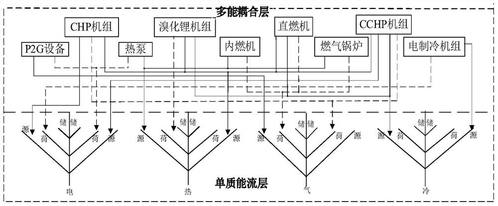
The invention provides a comprehensive energy system model and a construction method thereof, and the method comprises the steps: constructing an elementary substance energy flow layer and a multi-energy coupling layer, building the incidence relation between the elementary substance energy flow layer and the multi-energy coupling layer, and obtaining a comprehensive energy system. Different control systems can conveniently and flexibly generate information models of respective devices, the models are rapidly integrated after interaction, development and implementation of different applications of the comprehensive energy system are facilitated, and new device types are conveniently added. If the multi-energy coupling layer is ignored, the model is simplified into a plurality of mutually independent elementary substance energy flow systems, and respective control systems and applications of cold, hot and gas are met. And if the single-energy-flow transmission equipment is further ignored, the model is simplified into a traditional power system standardized model. And if the elementary substance energy flow layer is ignored, only the multi-energy coupling layer and related source load equipment are reserved, and the model is simplified into a common energy router model which can be used for scenes such as some small parks / buildings / distributed energy stations and the like.

Description

technical field [0001] The invention belongs to the technical field of integrated energy systems, and in particular relates to an integrated energy system model and a construction method thereof. Background technique [0002] The Energy Internet with the integrated energy system as the physical carrier is the development trend of the energy system. Compared with the traditional single energy system, multi-energy flow, multi-scale, and multi-agent are the important features of the integrated energy system. Different management subjects and modeling methods of different disciplines lead to the existence of information islands between different energy flows, resulting in the gap between energy flows. The multi-scale complementary and flexible capabilities cannot be fully tapped and utilized, which will affect the overall operating efficiency of the integrated energy system. Establish a standardized information interaction model, use a unified language to describe the integrate...

Claims


Application Information

Patent Timeline
Patent Type & Authority Applications(China)
IPC IPC(8): G06Q10/06G06Q50/06
CPCG06Q10/067G06Q50/06
Inventor 孙宏斌郭泰李强朱红夏天段丽娟刘永清朱正谊
Learn More