Automobile control device based on mobile phone inductive control
A sensory control and car control technology, applied in location information-based services, specific environment-based services, anti-theft vehicle accessories, etc., can solve the problem of not being able to conveniently check car-related information at any time, inconvenient use, user troubles, etc. question
- Summary
- Abstract
- Description
- Claims
- Application Information
AI Technical Summary
Problems solved by technology
Method used
Image
Examples
Embodiment 2
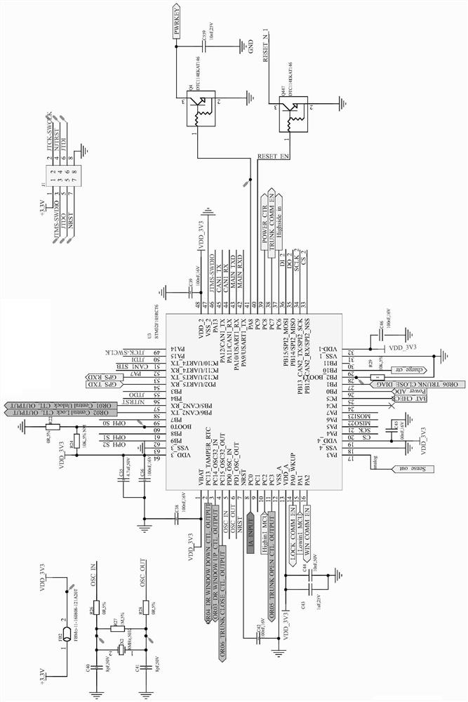
[0038] Example 2, such as figure 1 As shown, the 5 and 6 pins of the chip U3 are respectively connected to the 2 and 1 pins of the crystal oscillator X2 through the resistor R26 and the resistor R28, and the 2 and 1 pins of the crystal oscillator X2 are respectively grounded through the capacitors C40 and C41. Pins 46, 55, 7, 49, 56 and 50 of the chip U3 are respectively connected to pins 3, 5, 7, 2, 4 and 6 of the interface J1, and the model of the chip U3 is STM32F105RCT6.
[0039] In this embodiment, the chip U3 is the main chip, which is used to judge whether the mobile phone of an authorized user is approaching or leaving, to issue control models, or to issue control commands according to user instructions, and the interface J1 is used for debugging or programming of the chip U3.
Embodiment 3
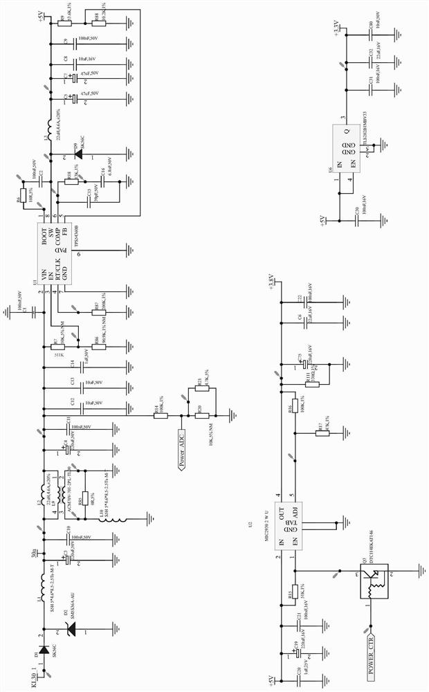
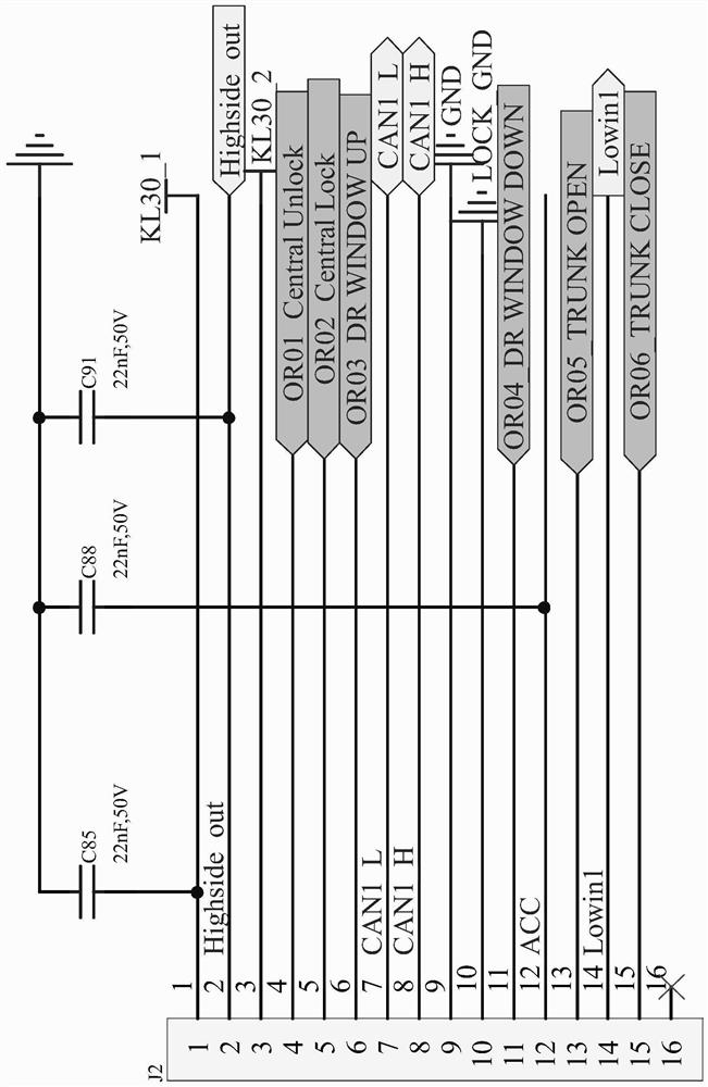
[0040] Example 3, such as figure 2 As shown, the power module includes chips U1, U2 and U6, the 2 pins of the chip U1 are connected to the 1 pin of the interface J2 through the inductor L2, L1 and diode D1, and the 1 and 4 tubes of the common mode inductor L9 The pins are respectively connected in parallel at both ends of the inductor L2, the 3 pins of the common mode inductor L9 are grounded through the inductor L10, the 2 pins are grounded, the 8 pins of the chip U1 are connected to a 5V voltage through the inductor L3, the chip Pin 2 of U2 is connected to a voltage of 5V, pin 4 is connected to a voltage of 3.8V, pins 1 and 4 of the chip U6 are connected to a voltage of 5V, pin 3 is connected to a voltage of 3.3V, and the model of the chip U1 is TPS54360B. The model of the chip U2 is MIC29302WU, and the model of the chip U6 is TLS202B1MBV33.
[0041] In this embodiment, the output voltage of the chip U1 is 5V, which supplies power for the subsequent stage of the circuit. A...
Embodiment 4
[0042] Example 4, such as Figure 4-5 As shown, the storage module includes a chip U10 and an SD card interface U30, the 1, 6, 2 and 5 pins of the chip U10 are respectively connected to the 20, 21, 22 and 23 pins of the chip U3, and the SD 2, 3, 5 and 7 pins of the card interface U30 are respectively connected to 33, 36, 34 and 35 pins of the chip U3, and the model of the chip U10 is MX25V4035FM1I; the indicating module includes light-emitting diodes LED444, LED3, LED4, LED5 and LED66, the anode of the light-emitting diode LED444 is connected to the 5V voltage, the cathode is connected to the 3-pin of the triode Q888 through the resistor R500, the cathode of the light-emitting diode LED3 is grounded through the resistor R39, and the anode is connected to the 3-pin of the triode Q7, Pin 2 of the triode Q7 is connected to a voltage of 5V, pin 1 is connected to pin 52 of the chip U3 through a resistor R5, the anode of the light-emitting diode LED4 is connected to a voltage of 5V,...
PUM
 Abstract
Description
Claims
Application Information
 - R&D
- Intellectual Property
- Life Sciences
- Materials
- Tech Scout
- Unparalleled Data Quality
- Higher Quality Content
- 60% Fewer Hallucinations
Browse by: Latest US Patents, China's latest patents, Technical Efficacy Thesaurus, Application Domain, Technology Topic, Popular Technical Reports.
© 2025 PatSnap. All rights reserved.Legal|Privacy policy|Modern Slavery Act Transparency Statement|Sitemap|About US| Contact US: help@patsnap.com


