Supercharge Your Innovation With Domain-Expert AI Agents!

Compression molding die for side surfaces of equal-density slender pipe fittings

A technology of side pressing and forming molds, applied in the direction of manufacturing tools, presses, etc., can solve the problems of unable to meet product design requirements, unable to press slender tube bodies with the same density of tube wall powder, and poor tube wall density, etc. It can achieve the effect of convenient and quick pressing, solving the problem of slender pipe fittings that cannot be of equal density, and simple structure.

Pending Publication Date: 2022-03-15
CHANGZHOU JIUYAJIU MACHINERY MFG
View PDF0 Cites 0 Cited by
  • Summary
  • Abstract
  • Description
  • Claims
  • Application Information

AI Technical Summary

Problems solved by technology

In this scheme, the inner and outer diameters of the tubular upper die and the pipe to be pressed are the same, the inner diameter of the lower tubular die is the same as the outer diameter of the pipe to be pressed, and the diameter of the mandrel shaft is the same as the inner diameter of the pipe to be pressed. A typical pipe body pressing scheme can only press pipe fittings with an aspect ratio of less than 3. For pipe fittings with an aspect ratio greater than 3, the wall density of the pipe body will have a large difference. The greater the density difference, the conventional pressing method is unable to press out the slender tube body with the same density of the tube wall powder, and the slender tube body with the same density is used for scientific research instruments and equipment in many fields such as aerospace, military industry, machinery, and medicine. The key parts of special equipment, especially the slender tube powder pressed parts with an aspect ratio greater than 5, cannot be achieved by conventional pressing in the overall industry.
Existing technical solutions cannot meet product design requirements

Method used


Image

  • Compression molding die for side surfaces of equal-density slender pipe fittings
  • Compression molding die for side surfaces of equal-density slender pipe fittings
  • Compression molding die for side surfaces of equal-density slender pipe fittings

Examples


Embodiment 1

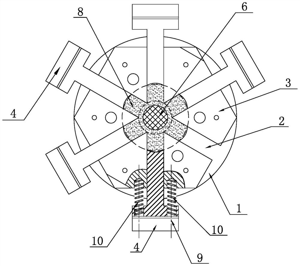
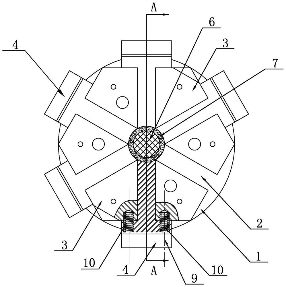
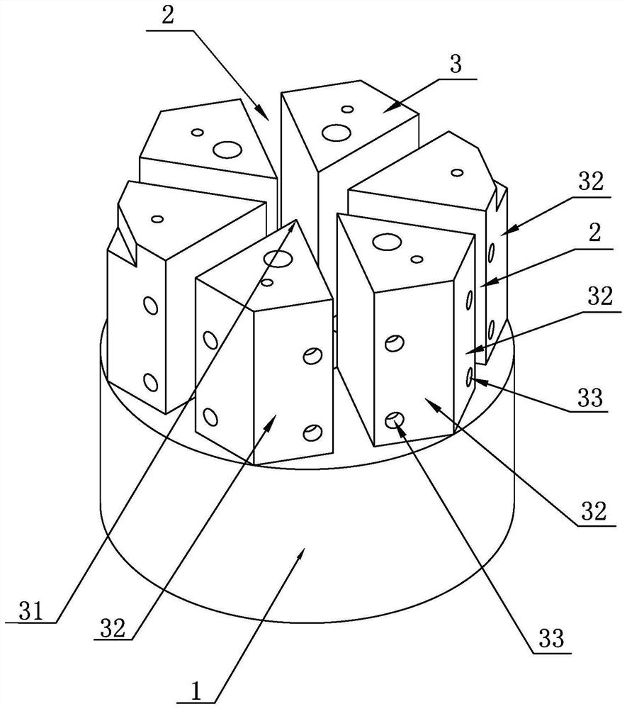
[0030] One kind of the elongated tubular member isopycnic side pressing mold, such as Figure 1-10 , The base including a seat, sliding grooves 2, six angular seat 3, six sides sliding pressing block 4, the pressing member 5 and the side mold mandrel 6, mold 6 fixedly mounted on the mandrel holder base 1 central location, six angular seat 3 disposed uniformly in the circumferential direction on the same circumference with the center of the mold with mandrels 6, and disposed at the upper end surface of the foundation block 1 is formed between two adjacent corners seat 3 a sliding groove 2, the outer diameter of the same sharp angle seat 3 seat diameter of the circle in which the tip 31 to be pressed to pipe 7; the side surface of the slide guide block 41 includes a pressing block 4, the pressure block 42, arc shaped 43, 44 and limit surface active surfaces 45, 43 forming the outer diameter of the arc diameter tube 7 to be pressed is the same, the side sliding pressing block 41 of th...

Embodiment 2

[0032] Example 2: Example 1 except that: the side surface and disposed radially slidably compact stopper structure 3 between different angular seat 4, in this example: a slide block 4 in the briquetting pressure side a mating side surface 42 and sharp corners 32 between the seat 3 of the return spring 10, the bottom of the slide 4 is provided on the side of the compact limiting chutes 47, the upper end surface of the seat base 1 is provided with a radial stop member 34. Such as Figure 8 Indicated.

[0033] In the above two embodiments, in order to reduce side movement of the sliding frictional resistance between the clamps 3 and 4 pointed base, with the slot to prevent the powders during pressing to squeeze the both sides, the jamming phenomenon will produce both , would cause a waste of powder, provided in the side surface 4 of the sliding pressing block 48 on the concave side with the powder leakage cavity 49, the depth can be set manually concave drain chamber 49 the powder is ...


PUM

PropertyMeasurementUnit
Concave depthaaaaaaaaaa

Abstract

A side face synchronous isobaric compression forming principle is adopted, the size of a powder containing cavity is determined according to the requirement of a long and thin pipe body to be pressed for the compression ratio of powder, and side face pressing is conducted on six side face sliding pressing blocks synchronously through side face pressing pieces. Under the action of the same side pressure, the tube wall powder compression density of the slender tube body is equal, and the length-diameter ratio of the slender tube body to be pressed is not limited theoretically according to the forming scheme provided by the invention. Experiments prove that the defects in the prior art can be ideally overcome. The side face pressing forming die for the equal-density slender pipe fitting is scientific and ingenious in design principle, simple in structure and convenient and fast to press, and the problem that the equal-density slender pipe fitting cannot be pressed through an existing pressing method is solved.

Description

Technical field: [0001] The present invention relates to a powder press molding technique tube press, and particularly to the elongated tubular member mold powder. Background technique: [0002] Pressing the powder tube is a hydraulic molding machine, press mold molding process in a specific repression powdery raw material, however, conventional pressing methods are commonly moved vertically by the hydraulic press and the mold tube, the tube tubular body mandrel and a die composed of mold press fit program. In this embodiment, the upper mold and the outer diameter of the tubular body of the tube to be pressed identical, the outer diameter of the inner diameter of the tube and the lower mold to be pressed tubular body, same as the inner diameter of the die mandrel with the tube to be pressed, which typical embodiment of the tube pressing member can press the tube of an aspect ratio of less than 3, the tube for aspect ratio greater than 3, the density of the wall of the tubular bod...

Claims


Application Information

Patent Timeline
IPC IPC(8): B30B15/02
CPCB30B15/022
Inventor 景星景卫平陈渊
Owner CHANGZHOU JIUYAJIU MACHINERY MFG
Features
  • R&D
  • Intellectual Property
  • Life Sciences
  • Materials
  • Tech Scout
  • Unparalleled Data Quality
  • Higher Quality Content
  • 60% Fewer Hallucinations
Learn More