
Boosting type dense-phase conveying system

A dense-phase conveying and boosting technology, which is applied to conveyors, conveying bulk materials, transportation and packaging, etc., can solve the problems of reduced airflow velocity, easy blockage of conveying efficiency, affecting the stability of dense-phase conveying, etc. The effect of reducing energy consumption, compact structure and difficult to disperse, improving molding speed and dense phase conveying efficiency

Active Publication Date: 2022-03-15
厦门安麦信自动化科技有限公司
View PDF7 Cites 2 Cited by
  • Summary
  • Abstract
  • Description
  • Claims
  • Application Information

AI Technical Summary

Problems solved by technology

[0004] The existing dense-phase conveying system generally adopts the connection mode of 3 tanks in series of atmospheric pressure silo, variable pressure silo and high pressure silo. The powder flows in the high-pressure silo. In the middle of the material flow, due to the consumption of the pipeline structure, the flow rate of the airflow is reduced, and the conveying efficiency is reduced. It is easy to cause blockage, and the powder in the material plug forming cavity cannot be pushed by the high-pressure gas. Dense material plug structure, under the action of dense phase static pressure difference, a large number of cavities mixed in the material plug will lead to the disintegration of the material plug, which will affect the stability of the entire dense phase transportation, so there are certain defects

Method used


Image

  • Boosting type dense-phase conveying system
  • Boosting type dense-phase conveying system
  • Boosting type dense-phase conveying system

Examples


Embodiment Construction

[0041] In order to make the object, technical solution and advantages of the present invention clearer, the present invention will be further described in detail below in combination with specific embodiments and with reference to the accompanying drawings. It should be noted that, in the case of no conflict, the embodiments of the present invention and the features in the embodiments can be combined with each other.

[0042] It is understood that these descriptions are exemplary only, and are not intended to limit the scope of the invention.

[0043] The push-assisted dense-phase conveying system provided by some embodiments of the present invention is described below with reference to the accompanying drawings.

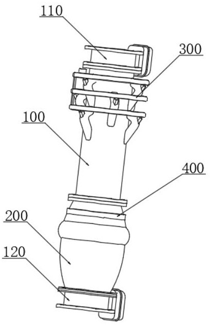
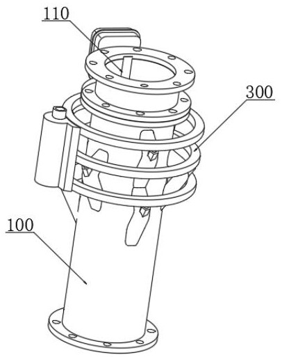
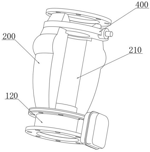
[0044] combine Figure 1-9 As shown, the booster dense-phase conveying system provided by the present invention includes: booster guide pipe 100, pulse material column compartment 200 and adjustable The guide mechanism 500 and the pulse air knife generator 400, th...


PUM


Abstract

The invention discloses a boosting type dense-phase conveying system which comprises a boosting material guide pipe, a pulse material column separation cabin, an adjustable guide mechanism and a pulse air knife generator, the adjustable guide mechanism and the pulse air knife generator are located in the boosting material guide pipe and the pulse material column separation cabin, and a pneumatic boosting mechanism is arranged on the outer side of the boosting material guide pipe. One end of the boosting material guide pipe is fixedly connected with the end part of the pulse material column separation cabin, the other end of the boosting material guide pipe and the other end of the pulse material column separation cabin are respectively provided with an inlet electric control valve and a material plug electric control valve, and the input end of the pneumatic boosting mechanism is fixedly connected with a boosting air pump mechanism. According to the material plug forming device, a novel boosting structure is additionally arranged, dense-phase conveying airflow is intervened and accelerated through boosting valve pipe structures evenly distributed on the surface of the boosting material guide pipe, dense-phase conveying is accelerated and boosted through boosting gas introduced from the outside, and the material plug forming speed and the dense-phase conveying efficiency are improved.

Description

technical field [0001] The invention relates to the technical field of dense phase conveying, in particular to a booster dense phase conveying system. Background technique [0002] Since the pneumatic conveying technology of solid materials in the pipeline began to be industrialized in the first half of the 19th century, it has been widely used in petroleum, chemical, pharmaceutical, grain, food, The transportation of powdery and granular materials exists in many industries such as electric power, building materials, metallurgy, and mining. During the transportation process, there are problems of mutual pollution of materials to the environment and the environment to materials. On the one hand, some materials are corrosive, irritating, etc. characteristics, conveying in an open state is harmful to the human body and polluting the environment, that is, the material pollutes the environment; on the other hand, some materials are easily oxidized and hygroscopic, and are transpo...

Claims


Application Information

Patent Timeline
IPC IPC(8): B65G53/34B65G53/58B65G53/52
CPCB65G53/34B65G53/58B65G53/521
Inventor 黄金满路密
Owner 厦门安麦信自动化科技有限公司
Learn More