
Spraying head with different spraying angles and washing machine

A technology with different angles and spray heads, which is applied to washing machines with containers, other washing machines, rinsing equipment, etc., can solve the problems of complete coverage of the front and rear ends of the inner cylinder, limited spray coverage, etc., to reduce clothing wear and tear. Deformation, guaranteed spray coverage area, good rinsing effect

Active Publication Date: 2022-03-18
GREE ELECTRIC APPLIANCES INC
View PDF9 Cites 0 Cited by
  • Summary
  • Abstract
  • Description
  • Claims
  • Application Information

AI Technical Summary

Problems solved by technology

[0004] The main purpose of the present invention is to provide a spray head and a washing machine with different spraying angles, so as to solve the problem of the spraying system of the washing machine in the prior art in realizing spraying. The spray coverage during the drift function is limited, and it is difficult to achieve complete coverage of the front and rear ends of the entire inner cylinder

Method used


Image

  • Spraying head with different spraying angles and washing machine
  • Spraying head with different spraying angles and washing machine
  • Spraying head with different spraying angles and washing machine

Examples


Embodiment 1

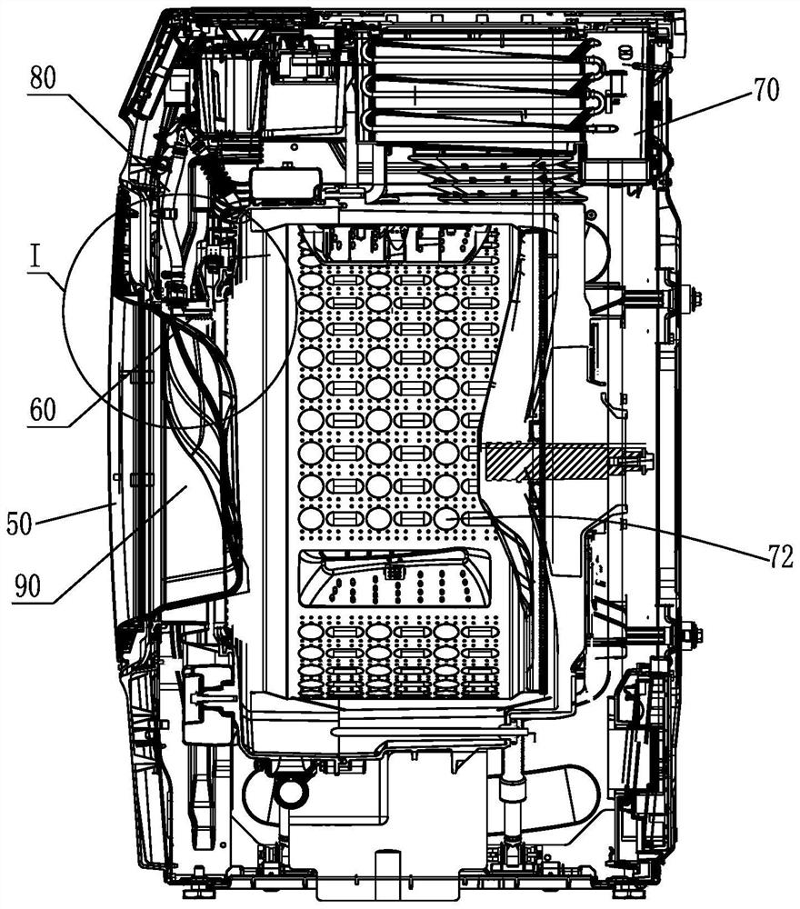
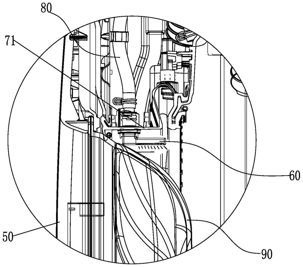
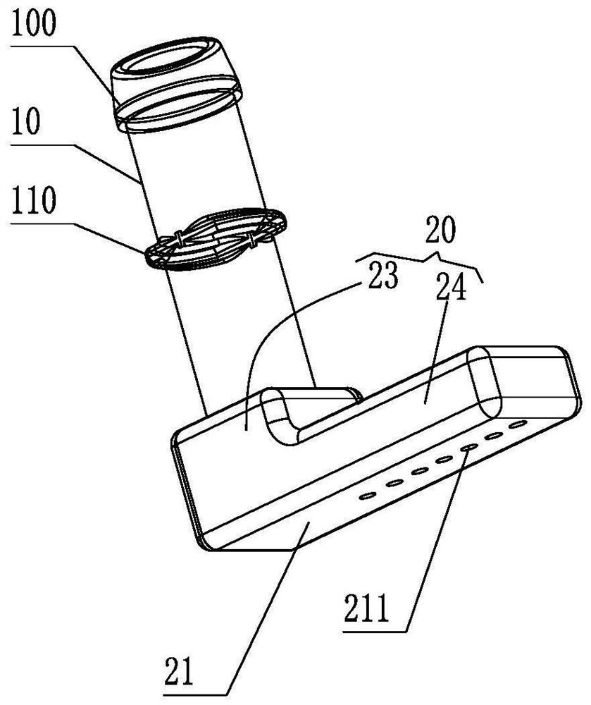
[0042] like Figure 3 to Figure 8 As shown, the sprinkler heads with different spray angles include a connecting pipe section 10 and a water spray structure 20, the connecting pipe section 10 is used to connect with the water supply pipeline; one end of the water spray structure 20 is connected with the connecting pipe section 10, and the water spray structure 20 has a spray The spray surface 21, the water spray structure 20 has a plurality of spray channels 22, and the plurality of spray channels 22 all extend to the spray surface 21 and have a plurality of spray holes 211 arranged at intervals at the spray surface 21; wherein, There is an included angle A between one end of the plurality of spray channels 22 communicating with the spray surface 21 and the spray surface 21 , and the included angle A gradually increases in the direction X away from the connecting pipe section 10 .

[0043] Using the spray heads with different spray angles in the present application can effecti...

Embodiment 2

[0073] It should be noted that the difference between this embodiment and the first embodiment is that, for example, Figure 9 to Figure 11 As shown, the shower head further includes a plurality of nozzles 30, the nozzles 30 are arranged on the spray surface 21, the plurality of nozzles 30 are arranged in a one-to-one correspondence with the plurality of spray holes 211, and each nozzle 30 corresponds to each corresponding spray The holes 211 communicate with each other, and the nozzles 30 extend along the extending direction of the corresponding spray channel 22 .

[0074] Optionally, the nozzle 30 is integrally formed with the water spray structure 20 .

[0075] Optionally, the distance between the nozzle 30 and the spray surface 21 is L, where 0.5mm≤L≤2mm. In this way, the direction of the water jet can be better guided, thereby ensuring the angle and range of the spray.

[0076] like Figure 3 to Figure 11 As shown, the connecting pipe section 10 of the sprinkler head 6...


PUM


Abstract

The invention provides a spraying head with different spraying angles and a washing machine, the spraying head with different spraying angles comprises a connecting pipe section and a water spraying structure, and the connecting pipe section is used for being connected with a water supply pipeline; one end of the water spraying structure is connected with the connecting pipe section, the water spraying structure is provided with a spraying face and a plurality of spraying channels, the spraying channels all extend to the spraying face, and the spraying face is provided with a plurality of spraying holes formed at intervals; an included angle A is formed between one end, communicated with the spraying surface, of each spraying channel and the spraying surface, and the included angle A is gradually increased in the direction X away from the connecting pipe section. The problems that in the prior art, when a spraying system of a washing machine achieves the spraying and bleaching functions, the spraying coverage range is limited, and the front end and the rear end of a whole inner barrel are difficult to completely cover are solved.

Description

technical field [0001] The invention relates to the technical field of household appliances, in particular to a spray head with different spray angles and a washing machine. Background technique [0002] At present, most washing machines will perform rinsing after completing the main washing process, so as to remove residual detergent, and then perform dehydration and drying. However, if there is too much rinsing, time will be wasted, which will undoubtedly increase the total washing time. In addition, the processes of rinsing, rinsing, washing, and draining all take a certain amount of time, and multiple dehydration increases the time for clothes to find a balance, which not only prolongs the total washing time, but also increases energy consumption such as power consumption. At the same time, in the rinsing stage, the drum also needs to be rotated to drive the clothes to be beaten or rubbed, which will increase the wear or deformation of the clothes to a certain extent. ...

Claims


Application Information

Patent Timeline
Patent Type & Authority Applications(China)
IPC IPC(8): D06F17/04D06F39/08D06F41/00
CPCD06F17/04D06F39/088D06F41/00
Inventor 黄国鹏熊传鑫王立乾伍晗刘梦辉李咏谦
Owner GREE ELECTRIC APPLIANCES INC
Learn More