Pet slice with ductility

A ductility and slicing technology, applied in the direction of testing the ductility and strength properties of materials, and using stable tension/pressure to test the strength of materials. Inconvenient slicing and other problems, to achieve the effect of reducing equipment use and sample anomalies, intuitive and convenient test data collection, and convenient classification and pick-and-place

Pending Publication Date: 2022-03-18
SUZHOU HEJI RONGDA NEW MATERIALS CO LTD
View PDF0 Cites 0 Cited by
  • Summary
  • Abstract
  • Description
  • Claims
  • Application Information

AI Technical Summary

Problems solved by technology

[0005] In order to make up for the shortcomings of the existing technology, it solves the problems that the existing pet slices are inconvenient for ductility testing, inconvenient to disassemble and slice, and are not conducive to sample classification and placement

Method used


Image

  • Pet slice with ductility
  • Pet slice with ductility
  • Pet slice with ductility

Examples


Embodiment 1

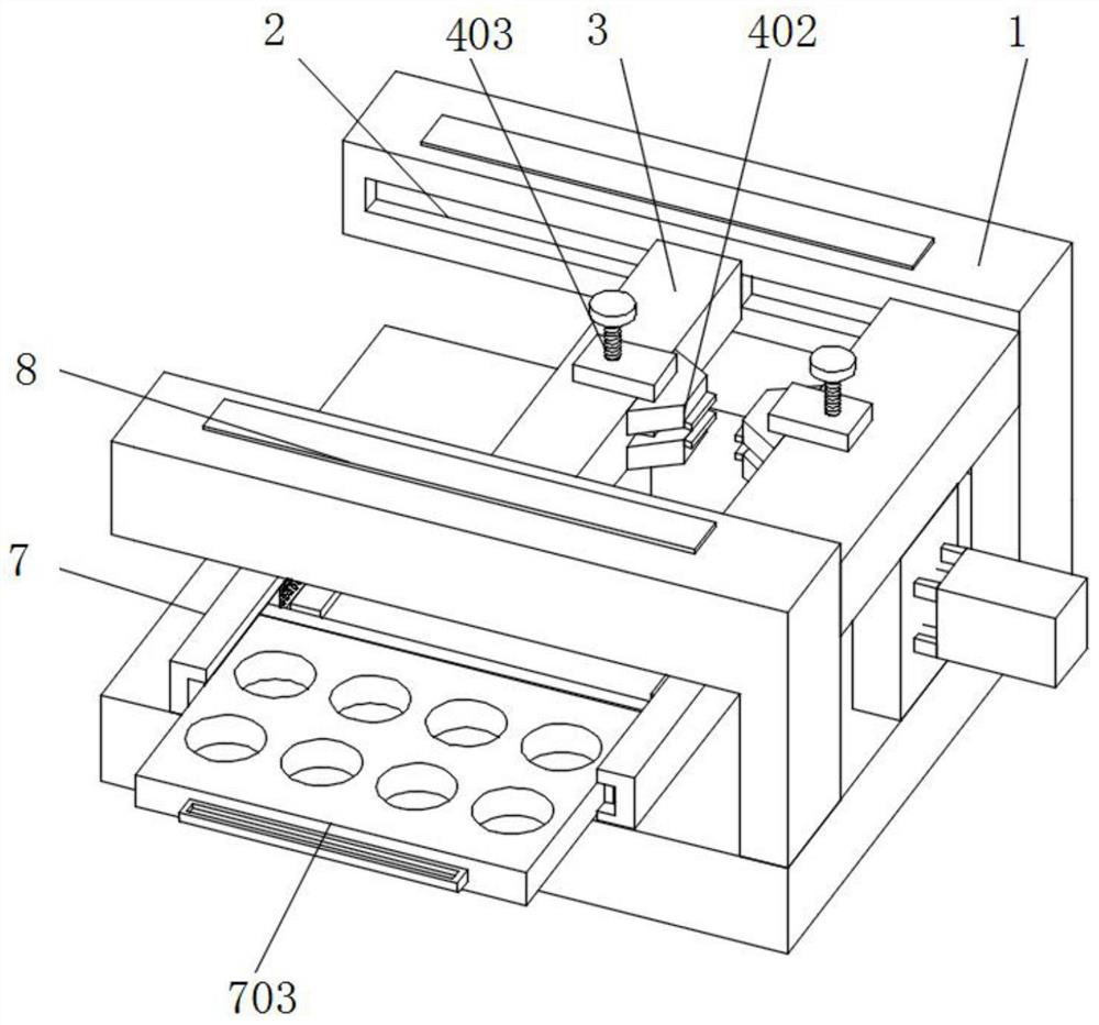
[0022] see Figure 1-2 As shown, a pet slice with ductility includes a main body 1, a chute 2, a sliding frame 3, a clamping mechanism 4, a connecting plate 5, a transmission rod 6, a sliding mechanism 7 and a scale 8, and the inner side of the main body 1 is provided with chute 2, and the inside of the chute 2 is connected with a sliding frame 3, and the outside of the sliding frame 3 is provided with a gripping mechanism 4, and the bottom of the sliding frame 3 is provided with a connecting plate 5, and the inside of the connecting plate 5 is penetrated by a transmission rod 6;

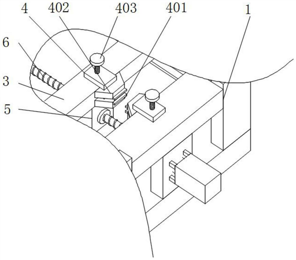
[0023] The clamping mechanism 4 includes a lower biting block 401, an upper biting block 402 and a screw rod 403, an upper biting block 402 is arranged above the lower biting block 401, and a screw rod 403 runs through the inside of the upper biting block 402;

[0024] The upper bite block 402 forms a lift structure between the screw rod 403 and the lower bite block 401, and the upper bite block 40...

Embodiment 2

[0027] see figure 1 with image 3 As shown, a pet slice with ductility, a sliding mechanism 7 is arranged under the chute 2, and a scale 8 is arranged on the top of the main body 1;

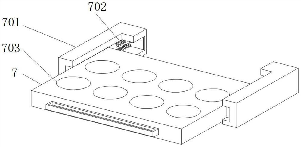
[0028] The sliding mechanism 7 includes a slide rail 701, a spring 702 and a collection groove 703, the inside of the slide rail 701 is provided with a spring 702, and the end of the spring 702 is connected to the collection groove 703;

[0029] The collection tank 703 forms a lifting structure through the spring 702 and the slide rail 701, and the slide rail 701 is arranged symmetrically with respect to the central axis of the collection tank 703. Slide and pull out along the slide rail 701.

[0030] Working principle: First, the slice is clamped and fixed by the clamping mechanism 4, the slice is placed between the upper bite block 402 and the lower bite block 401, and the position of the upper bite block 402 is adjusted by rotating the top screw 403, which can The slices are clamped and fix...


PUM


Abstract

The invention belongs to the field of pet slices, and particularly relates to a pet slice with ductility, which comprises a base, a mounting frame, a main body and a scale, a sliding groove is formed in the inner side of the main body, a sliding frame is connected to the interior of the sliding groove, a clenching mechanism is arranged on the outer side of the sliding frame, a connecting plate is arranged at the bottom of the sliding frame, and the connecting plate is connected with the scale. A transmission rod penetrates through the interior of the connecting plate, a sliding mechanism is arranged below the sliding groove, and the ruler is arranged at the top of the main body. The clamping mechanism is arranged, a slice is clamped and fixed between an upper clamping block and a lower clamping block, the slice can be flexibly disassembled and assembled, clamping stability can be guaranteed through a screw, follow-up ductility testing operation of the equipment is facilitated, clamping is flexible and stable, a collecting tank is additionally arranged, detection products are classified and placed in the collecting tank, and the detection efficiency is improved. When needed, the collecting groove can be pulled out along the sliding rail in a sliding mode, different samples in the sliding rail can be conveniently taken and classified, and taking and placing are flexible.

Description

technical field [0001] The invention relates to the field of pet slices, in particular to a malleable pet slice. Background technique [0002] The use of polyester now includes fibers, various containers, packaging materials, films, films, engineering plastics and other fields. Polyester plays a greater role in production, new materials and plastic products. It has a great role in road general cargo transportation. The role of polyester chip processing is an important part. [0003] Existing pet slices are inconvenient for ductility testing, inconvenient for disassembly and assembly of slices, and unfavorable for sorting and taking and placing of samples, which have a certain impact on use. [0004] Therefore, a malleable pet slice is proposed to address the above problems. Contents of the invention [0005] In order to make up for the deficiencies of the existing technology, the problems that the existing pet slices are inconvenient for ductility testing, inconvenient f...

Claims


Application Information

Patent Timeline
Patent Type & Authority Applications(China)
IPC IPC(8): G01N3/28G01N3/04G01N3/08
CPCG01N3/28G01N3/04G01N3/08
Inventor 尤郁明刘林强宣继良
Owner SUZHOU HEJI RONGDA NEW MATERIALS CO LTD
Why Eureka
Try Eureka