Detection method and device for ultrasonic sensor of robot
An ultrasonic and sensor technology, applied in the field of robotics, can solve problems such as low detection accuracy
- Summary
- Abstract
- Description
- Claims
- Application Information
AI Technical Summary
Problems solved by technology
Method used
Image
Examples
Embodiment 1
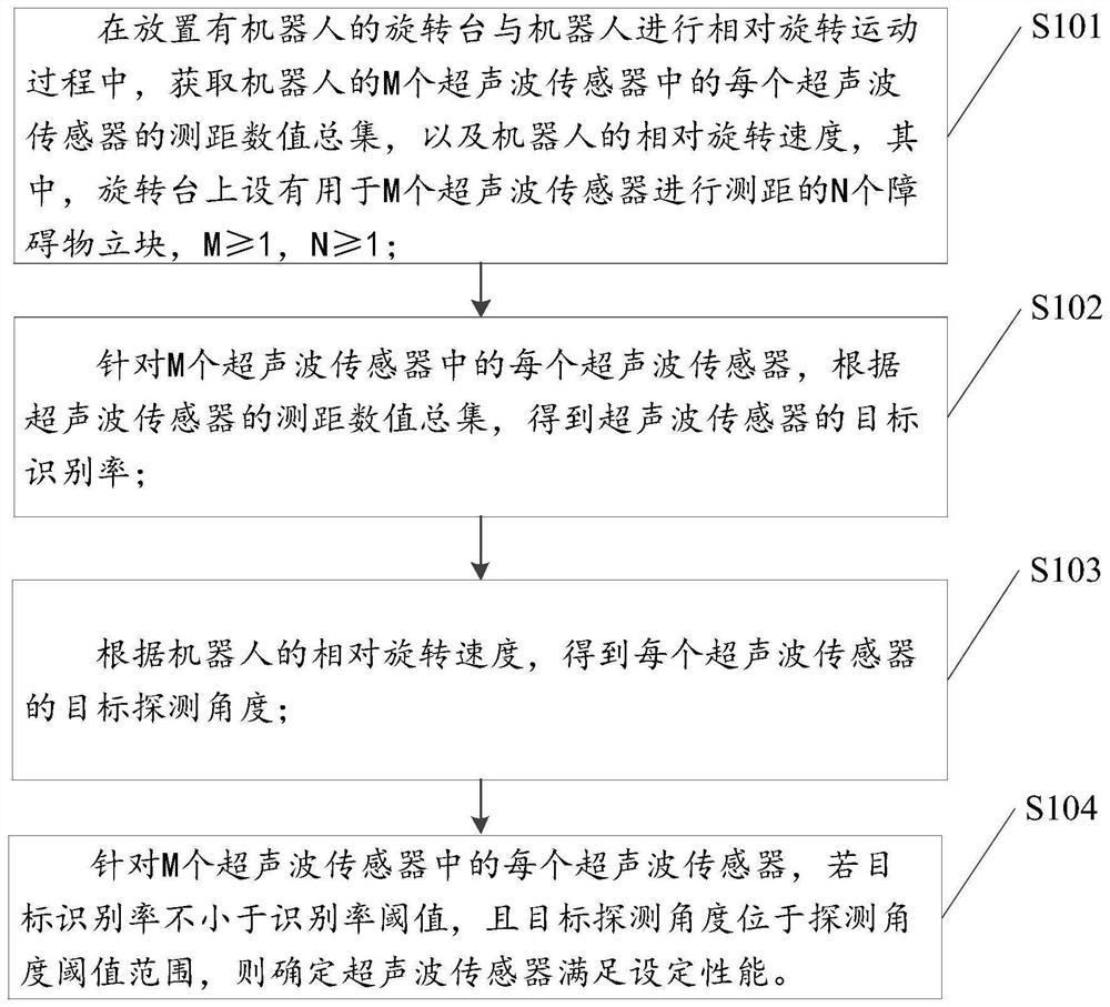
[0043] The first embodiment of the present invention provides a detection method of an ultrasonic sensor of a robot, such as figure 1 shown, including:
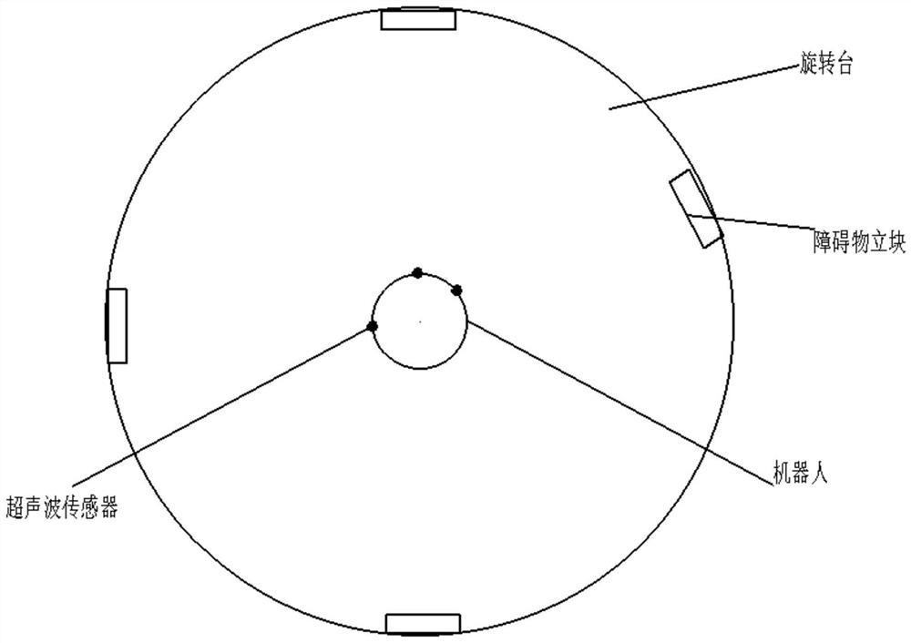
[0044] S101. During the relative rotational movement between the rotating table on which the robot is placed and the robot, obtain the total set of ranging values of each of the M ultrasonic sensors of the robot, and the relative rotational speed of the robot, wherein, on the rotating table There are N obstacle blocks for distance measurement by M ultrasonic sensors, M≥1, N≥1;
[0045] S102, for each of the M ultrasonic sensors, according to the total set of ranging values of the ultrasonic sensors, the target recognition rate of the ultrasonic sensors is obtained;
[0046]S103, according to the relative rotation speed of the robot, obtain the target detection angle of each ultrasonic sensor;
[0047] S104. For each ultrasonic sensor in the M ultrasonic sensors, if the target recognition rate is not less than the recogn...
Embodiment 2
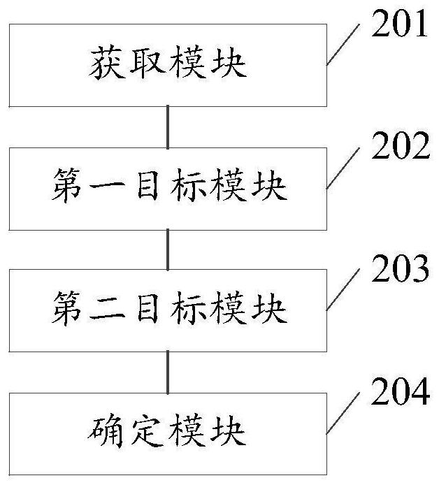
[0083] Based on the same inventive concept, the second embodiment of the present invention also provides a detection device for an ultrasonic sensor of a robot, such as image 3 shown, including:
[0084] The obtaining module 201 is used to obtain the total set of ranging values of each of the M ultrasonic sensors of the robot during the relative rotational movement between the rotating table on which the robot is placed and the robot, and the The relative rotation speed, wherein, the rotating table is provided with N obstacle vertical blocks for the distance measurement of the M ultrasonic sensors, M≥1, N≥1;
[0085] The first target module 202 is configured to, for each of the M ultrasonic sensors, obtain the target recognition rate of the ultrasonic sensors according to the total set of ranging values of the ultrasonic sensors;
[0086] The second target module 203 is configured to obtain the target detection angle of each ultrasonic sensor according to the relative ro...
Embodiment 3
[0105] Based on the same inventive concept, the third embodiment of the present invention also provides a robot, such as Figure 4 As shown, it includes a memory 304, a processor 302, and a computer program stored on the memory 304 and operable on the processor 302. When the processor 302 executes the program, any of the detection methods of the ultrasonic sensor of the above-mentioned robot is realized. the steps of a method.
[0106] Among them, in Figure 4 In, bus architecture (represented by bus 300), bus 300 may include any number of interconnected buses and bridges, bus 300 will include one or more processors represented by processor 302 and various types of memory represented by memory 304 circuits linked together. The bus 300 may also link together various other circuits, such as peripherals, voltage regulators, and power management circuits, etc., which are well known in the art and thus will not be further described herein. The bus interface 306 provides an inter...
PUM
 Abstract
Description
Claims
Application Information
 - R&D
- Intellectual Property
- Life Sciences
- Materials
- Tech Scout
- Unparalleled Data Quality
- Higher Quality Content
- 60% Fewer Hallucinations
Browse by: Latest US Patents, China's latest patents, Technical Efficacy Thesaurus, Application Domain, Technology Topic, Popular Technical Reports.
© 2025 PatSnap. All rights reserved.Legal|Privacy policy|Modern Slavery Act Transparency Statement|Sitemap|About US| Contact US: help@patsnap.com


