Light path debugging method and system for motor vehicle pollution detection equipment

A pollution detection and debugging method technology, applied in optics, measuring devices, optical components, etc., can solve problems such as danger, difficulty in dimming, and long time consumption, and achieve the effect of saving labor costs and time costs, and solving difficulties in optical path calibration

Pending Publication Date: 2022-03-18
ANHUI QINGYU PHOTOELECTRIC TECH
View PDF0 Cites 0 Cited by
  • Summary
  • Abstract
  • Description
  • Claims
  • Application Information

AI Technical Summary

Problems solved by technology

It is difficult to adjust the light during on-site installation. This method has requirements for the environment and the optical path of equipment installation. It is required that the environment is relatively dark and the optical path of the optical path is short. Cooperate to debug: one person debugs the instrument, and the other needs to check the position of the light in real time. It takes a long time to find the position of the ultraviolet spectrum, and it is necessary to coordinate with the traffic department on the running time of road vehicles
[0004] The open traffic atmospheric environment monitoring system is used for testing: it is generally installed on the roadside of the road, consisting of a main engine and an auxiliary machine, so that the optical path passes through t

Method used


Image

  • Light path debugging method and system for motor vehicle pollution detection equipment
  • Light path debugging method and system for motor vehicle pollution detection equipment
  • Light path debugging method and system for motor vehicle pollution detection equipment

Examples


Embodiment 1

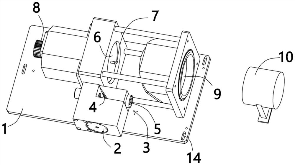
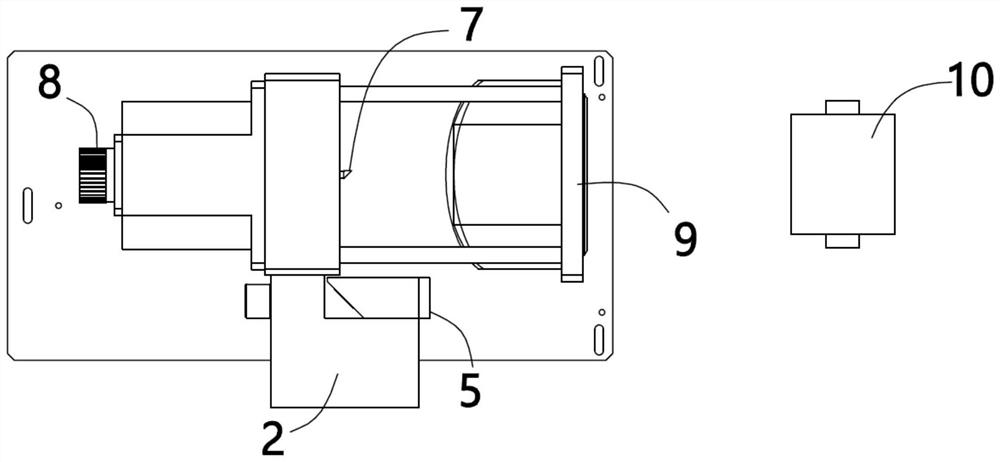
[0042] see Figure 1 to Figure 3 , the present invention provides a technical solution:

[0043] A method for debugging an optical path of a vehicle pollution detection device, comprising:

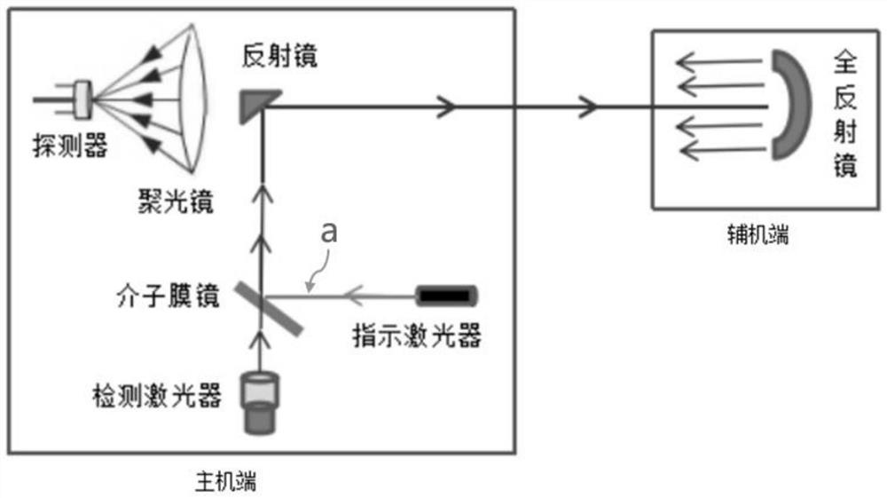
[0044] A beam of infrared laser is emitted from one side to the other side after being reflected, forming the first optical path;

[0045] emitting a beam of visible light into the first light path;

[0046] Adjust the incident angle of visible light so that the visible light remains coaxial with the first optical path, and then reflect the spectrum of the infrared laser back to the original path;

[0047] The light signal of the reflected infrared laser is converted into an electrical signal, and after processing, the concentration of pollutants is calculated.

[0048] The system of this embodiment includes two major parts, the main machine end and the auxiliary machine end, which are respectively located on both sides of the road; the components contained in the main machine end are i...

Embodiment 2

[0052] see figure 1 or Figure 4 , which is basically the same as Example 1, with a slight difference:

[0053] A beam of visible light is emitted into the first optical path, and the visible light is also green light, which is emitted from the auxiliary machine end, that is, the indicator laser 5 is used to emit green light, and the indicator laser 5 is located at the auxiliary machine end side, specifically at the total reflection on the axis in the mirror 10, and then only need to refer to the light emitted by the indicator laser 5 to adjust the height and direction of the bottom plate 1: make the green light reflected by the meson film mirror 4 coincide with the marking line a, which means that the indicator laser The light remains coaxial with the light of the detection laser.

Embodiment 3

[0055] see Figure 5 to Figure 7 , which is basically the same as Example 1, with a slight difference:

[0056] The deuterium lamp 11 is used for the instruction laser emitting device 3, and the spectrometer 13 is used for the detection device. After the spectrum reaches the spectrometer, the optical signal is converted into an electrical signal, and then processed by a circuit to calculate the concentration of pollutants. The light emitted by the deuterium lamp 11 is first collimated by the collimating mirror 12 located between the meson film mirror 4 and the deuterium lamp 11 and then incident on the meson film mirror 4 .


PUM


Abstract

The invention provides a light path debugging method and system for motor vehicle pollution detection equipment, and the method comprises the steps: transmitting a beam of infrared laser from one side to the other side after reflection, and forming a first light path; emitting a beam of visible light into a first light path; the incident angle of the visible light is adjusted, so that the visible light and the first light path are kept coaxial, and then the spectrum of the infrared laser is reflected back along the original path; the reflected infrared laser light signal is converted into an electric signal, and the pollutant concentration is calculated through processing. According to the invention, the defects that the light path debugging of the traditional equipment for detecting the pollution of the motor vehicle is limited by environmental conditions, the debugging time is long, the number of personnel is large, the process is complicated and the potential safety hazard is large during debugging are overcome, and when the infrared spectral line is debugged outdoors, a light beam quality analyzer, a spectrum color card and other equipment are not needed to search the light position; and optical path debugging can be carried out at any time in 24 hours all day, and the problem that the optical path is difficult to calibrate in the equipment installation and operation process is solved.

Description

technical field [0001] The invention relates to the technical field of motor vehicle pollution detection, in particular to an optical path debugging method and system for motor vehicle pollution detection equipment. Background technique [0002] Pollution from mobile sources such as motor vehicles has become an important source of air pollution, and the importance of pollution prevention and control from mobile sources has become increasingly prominent. Pollutants emitted by motor vehicles have brought serious pollution to the atmospheric environment. At present, the main products for measuring motor vehicle pollution include motor vehicle exhaust remote sensing detection system and open traffic atmospheric environment monitoring system, which use ultraviolet spectrum absorption technology to monitor pollutants in the ultraviolet band. [0003] Ultraviolet spectrum absorption technology is used to test motor vehicle pollution: all of which are in the invisible light band, o...

Claims


Application Information

Patent Timeline
IPC IPC(8): G02B27/62G01N21/01G01N21/3504
CPCG02B27/62G01N21/01G01N21/3504
Inventor 陈庆华沈鹏
Owner ANHUI QINGYU PHOTOELECTRIC TECH
Why Eureka
Try Eureka