Crushing tool for powder coating production

A powder coating and cutting tool technology, applied in grain processing and other directions, can solve problems such as inconvenient disassembly, and achieve the effects of increasing work efficiency, improving stability, and increasing crushing area.

Inactive Publication Date: 2022-03-22
HUNAN LIANXIN SCI & TECH CO LTD
View PDF0 Cites 0 Cited by
  • Summary
  • Abstract
  • Description
  • Claims
  • Application Information

AI Technical Summary

Problems solved by technology

[0005] The invention provides a cutting tool for crushing processing produced by powder coatings, which solves the problem that the cutting tools for crushing processing produced by powder coatings are inconvenient to disassemble

Method used


Image

  • Crushing tool for powder coating production
  • Crushing tool for powder coating production
  • Crushing tool for powder coating production

Examples


no. 1 example

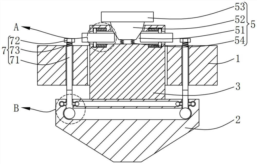
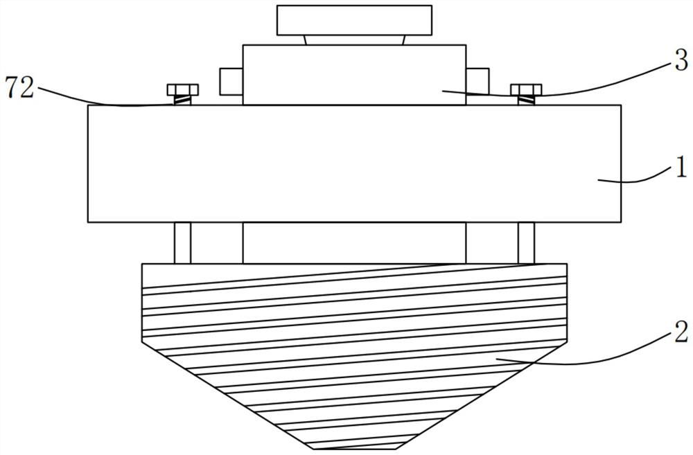
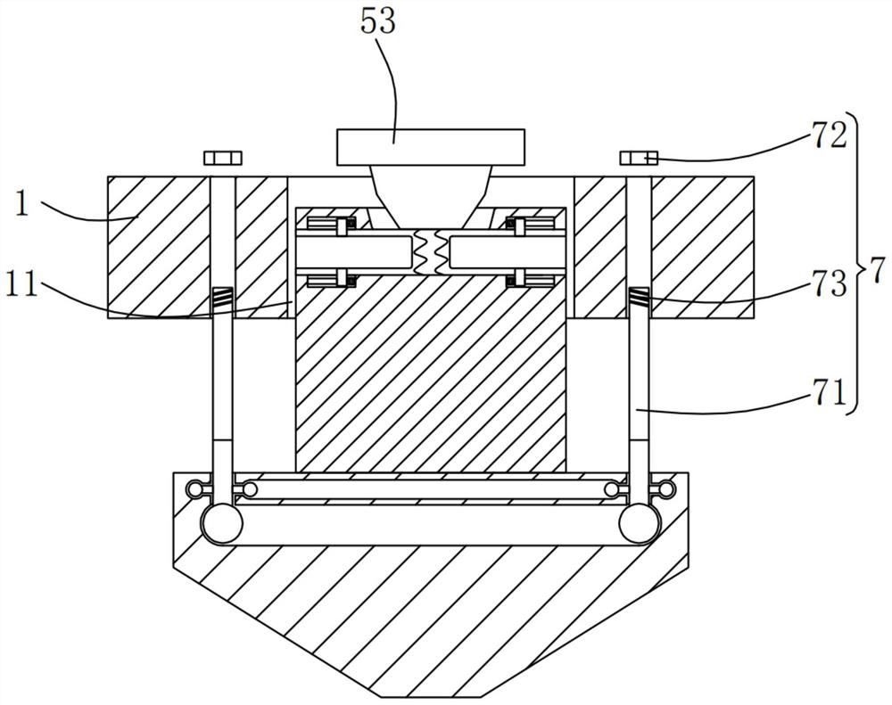
[0033] Please refer to Figure 1-Figure 5 ,in, figure 1 A schematic structural view of the first embodiment of the pulverizing tool produced by the powder coating provided by the present invention; figure 2 for figure 1 The appearance diagram shown; image 3 for figure 1 Schematic diagram of the structure during installation or disassembly; Figure 4 for figure 1 The enlarged schematic diagram of part A shown; Figure 5 for figure 1 The enlarged schematic diagram of part B is shown. The cutting tool for powder coating production includes: a base 1, a limiting assembly 6 and a connecting assembly 7, the limiting assembly 6 is arranged on the base 1 through the connecting assembly 7;

[0034] The first blade 2, the first blade 2 is arranged on the bottom of the base 1 through the positioning hole 11;

[0035] A connecting rod 3, the connecting rod 3 slides on the base 1, and the bottom end of the connecting rod 3 is fixedly connected with the first blade 2;

[0036] T...

no. 2 example

[0058] see Figure 6-Figure 7 , based on the pulverizing tool produced by powder coating provided in the first embodiment of the present application, the second embodiment of the present application proposes another kind of pulverizing tool produced by powder coating. The second embodiment is only a preferred mode of the first embodiment, and the implementation of the second embodiment will not affect the independent implementation of the first embodiment.

[0059] Specifically, the difference between the pulverizing tool produced by the powder coating provided by the second embodiment of the present application is that the pulverized tool produced by the powder coating also includes: a rotating assembly 8, and the rotating assembly 8 includes a plurality of Rectangular slots 81 , the inner walls of the plurality of rectangular slots 81 are rotatably connected with rotating rods 82 , and the plurality of rotating rods 82 are fixedly connected with second blades 83 .

[0060] ...


PUM


Abstract

The invention provides a crushing tool for powder coating production. The crushing tool comprises a base; the first blade is arranged at the bottom of the base; the connecting rod slides on the base, and the bottom end of the connecting rod is fixedly connected with the first blade; the crushing machining tool for powder coating production comprises a base, a connecting rod is arranged on the base, a clamping assembly is arranged on the connecting rod, the clamping assembly comprises two clamping grooves, and the inner surfaces of the two clamping grooves are both slidably connected with clamping rods. The moving assembly drives the clamping assembly to clamp the connecting rod, so that the first blade is stably connected to the base, the limiting assembly limits the first blade, the connecting assembly enables the limiting assembly to be stably connected to the base, the stability of the first blade is improved, and therefore the first blade is fixed to the base.

Description

technical field [0001] The invention relates to the field of knives for crushing and processing produced by powder coatings, in particular to a cutter for crushing and processing produced by powder coatings. Background technique [0002] Powder coating is a solid powder synthetic resin coating composed of solid resin and pigments, fillers and additives. Unlike ordinary solvent-based paints and water-based paints, its dispersion medium is not solvent and water, but air. It has the characteristics of no solvent pollution, 100% film formation and low energy consumption. [0003] In the pulverization process of powder coating production, different tools are required due to different use environments and different materials. However, the pulverization processing knives produced by powder coatings are generally fixed directly on the base when installed. After using the blade for a long time, the blade needs to be replaced. , but the existing blades are inconvenient to replace, a...

Claims


Application Information

Patent Timeline
Patent Type & Authority Applications(China)
IPC IPC(8): B02C18/10B02C18/18
CPCB02C18/10B02C18/18
Inventor 夏连心杨立兵朱满子方志旺
Owner HUNAN LIANXIN SCI & TECH CO LTD
Why Eureka
Try Eureka