Continuous flow centrifugal device

A technology of centrifugal device and body, applied in centrifuges and other directions, can solve problems such as generation of debris and contamination of raw liquid, and achieve the effects of improving safety, reducing waste, and reducing the probability of debris contamination

Pending Publication Date: 2022-03-22
上海泰闪科技有限公司
View PDF0 Cites 0 Cited by
  • Summary
  • Abstract
  • Description
  • Claims
  • Application Information

AI Technical Summary

Problems solved by technology

[0004] In view of the above-mentioned related technologies, the inventors have found that there are the following defects: mechanical seals are generally used between the rotating bowl and the sealing cover, such as sealing rings or sealing rings, etc., and debris is likely to be generated after wear and tear between the rotating bowl and the sealing member , and these debris are easy to enter the original solution located in the rotating bowl and cause pollution to the original solution, which leads to the safety of the original solution

Method used


Image

  • Continuous flow centrifugal device
  • Continuous flow centrifugal device
  • Continuous flow centrifugal device

Examples


Embodiment Construction

[0069] Below in conjunction with accompanying drawing 1-8, the present application is described in further detail.

[0070] The embodiment of the present application discloses a continuous flow centrifugal device.

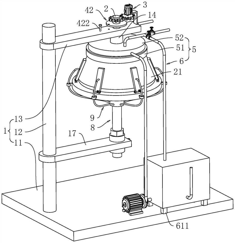
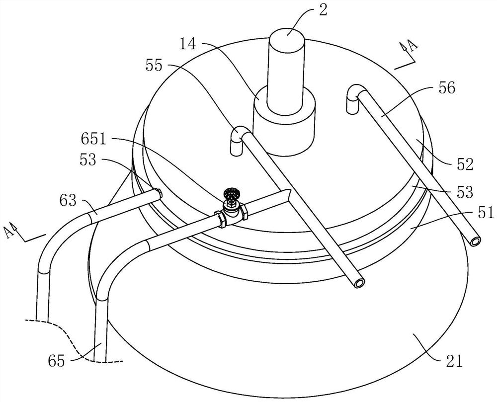
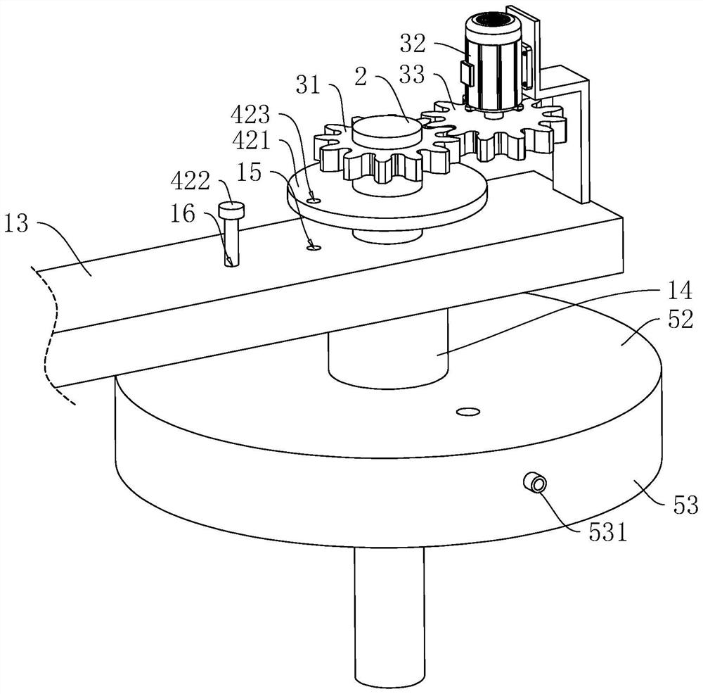
[0071] refer to figure 1 , the continuous flow centrifugal device includes a body 1, a rotating shaft 2 mounted on the body 1, a rotating bowl 21 is detachably arranged on the rotating shaft 2 through a connecting assembly 4 for separating the stock solution, and the body 1 is provided with a driving rotating bowl 21 to rotate The driving device 3, the body 1 is provided with a sealing device 5 for sealing the rotating bowl 21 and a supporting device 8 for supporting the rotating bowl 21.

[0072] refer to figure 1 and figure 2 , the body 1 includes a machine platform 11, a support rod 12 and a mounting plate 13, the support rod 12 is fixedly mounted on the upper surface of the machine platform 11 and is in a vertical state, one end of the mounting plate 13 is ...


PUM


Abstract

The invention relates to a continuous flow centrifugal device, and relates to the technical field of centrifugal devices, the continuous flow centrifugal device comprises a machine body and a rotating bowl, a driving device for driving the rotating bowl to rotate is arranged on the machine body, a sealing device is arranged on the machine body, and the sealing device comprises an annular box arranged on the rotating bowl; the fixed cover is arranged on the machine body and extends into the annular box, a sealing cavity is formed between the fixed cover and the inner side wall of the annular box, and a liquid inlet pipe and a liquid outlet pipe which are used for liquid inlet and liquid outlet respectively are arranged on the fixed cover; the liquid supply mechanism is arranged on the machine body and used for adding liquid into the sealing cavity to seal the rotating bowl. The rotating bowl and the fixed cover are physically separated through the liquid, so that the probability of abrasion caused by rotation of the rotating bowl and the sealing piece is reduced under the condition that the sealing function is achieved, the probability that the stock solution is polluted by chippings is reduced, and the safety of the stock solution is improved.

Description

technical field [0001] The present application relates to the technical field of centrifugal devices, in particular to a continuous flow centrifugal device. Background technique [0002] A centrifuge is a machine that uses centrifugal force to separate components in a mixture of liquid and solid particles or liquid and liquid; the centrifuge is mainly used to separate the solid particles in the suspension from the liquid, or to separate the two densities in the emulsion , and separate the immiscible liquids. [0003] In the related art, a continuous flow centrifuge includes a body and a rotating bowl arranged on the body through the rotation of a rotating shaft. The body is provided with a sealing cover for sealing the rotating bowl. The rotating bowl is provided with and the liquid inlet pipe and liquid discharge pipe for discharging liquid. The body is provided with a driving device for driving the rotating bowl; The final stock solution is discharged through the dischar...

Claims


Application Information

Patent Timeline
Patent Type & Authority Applications(China)
IPC IPC(8): B04B7/02B04B7/08B04B11/04B04B9/12
CPCB04B7/02B04B7/08B04B11/04B04B9/12
Inventor 宋大川邱维达
Owner 上海泰闪科技有限公司
Why Eureka
Try Eureka