Novel mold fixing device convenient to use in electrical automatic production line
An electrical automation, new mold technology, applied in the direction of forming tools, manufacturing tools, metal processing equipment, etc., can solve the problems of low mold processing efficiency, inconvenient automatic adjustment of position, unable to stably support mold processing, etc., to improve efficiency and improve stability. sexual effect
- Summary
- Abstract
- Description
- Claims
- Application Information
AI Technical Summary
Problems solved by technology
Method used
Image

Examples
example 1
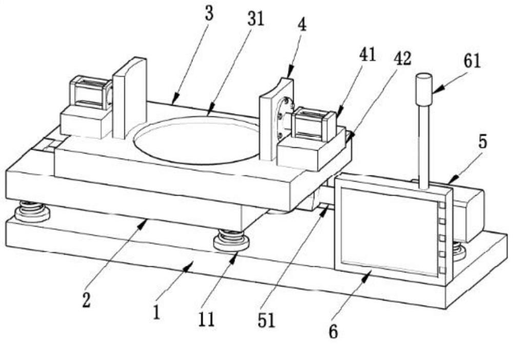
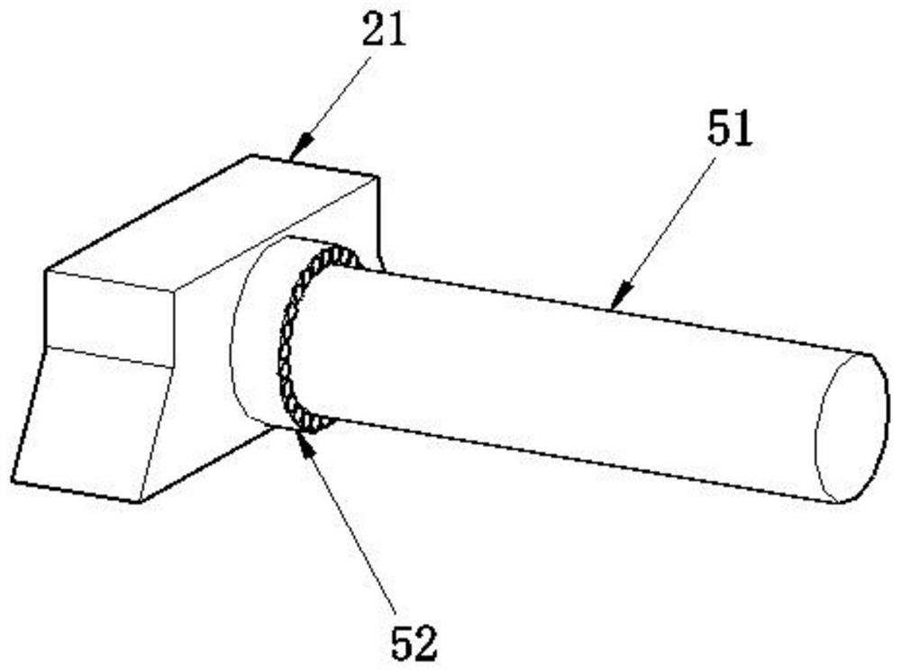
[0031] The embodiment of the present invention provides a technical solution: a new type of mold fixing device that is convenient for use in an electrical automation production line. The middle of the bottom of the mold support plate 3 is fixed with a slider 32, the slider 32 is slidably connected to the middle of the top of the fixed plate 2, the inside of the slider 32 is connected with a lead screw 51, the right end of the lead screw 51 Connected with drive motor 5, the bottom of described drive motor 5 and the bottom corner end of described fixed plate 2 are all welded with spring column 12, and the bottom of described spring column 12 is fixedly provided with EVA block 11, and described EVA block 11 is fixed on the top of the bottom plate 1, and a mold placement groove 31 is provided in the middle of the top of the mold support plate 3, which is suitable for various mold structures. Slidingly connected to the inside of the chute 22, and the slider 32 and the chute 22 are ...
example 2
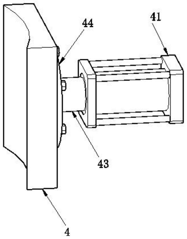
[0033]The embodiment of the present invention provides a technical solution: a new type of mold fixing device that is convenient for use in an electric automation production line. There is a push rod 43, the outer end of the push rod 43 is connected with an electric push rod device 41, the bottom of the electric push rod device 41 is fixedly provided with a fixed block 42, and the fixed block 42 is fixed on the bottom of the mold support plate 3 At both ends of the top, the inner end of the positioning and fixing plate 4 is an arc-shaped structure, which is stably fitted and clamped and positioned, and is non-slip and wear-resistant; the inner end of the push rod 43 is welded with a mounting plate 44, and the inner side of the mounting plate 44 The end is connected to the middle of the outer end of the positioning and fixing plate 4 by bolts, which is convenient to directly adopt tools to disassemble and assemble on the outer end of the positioning and fixing plate 4, which is ...
example 3
[0035] The embodiment of the present invention provides a technical solution: a new type of mold fixing device that is convenient for use in an electric automation production line. The front right end of the bottom plate 1 is fixed with a control panel 6, an intelligent control device circuit, and the control panel 6. The top is electrically connected with a warning light 61 through the bracket, which is a safety warning to avoid equipment damage and cannot be known. The control panel 6 is electrically connected to the electric push rod device 41 and the drive motor 5, which is convenient for intelligently controlling the electric push rod device 41 and the drive motor. 5. The front end of the control panel 6 is set on the touch screen, and the right end of the touch screen is distributed with buttons, which are more convenient to touch and press, and the design is reasonable.
[0036] Working principle: the slider 32 fixed in the middle of the bottom of the mold support plate ...
PUM
 Abstract
Description
Claims
Application Information
 - R&D
- Intellectual Property
- Life Sciences
- Materials
- Tech Scout
- Unparalleled Data Quality
- Higher Quality Content
- 60% Fewer Hallucinations
Browse by: Latest US Patents, China's latest patents, Technical Efficacy Thesaurus, Application Domain, Technology Topic, Popular Technical Reports.
© 2025 PatSnap. All rights reserved.Legal|Privacy policy|Modern Slavery Act Transparency Statement|Sitemap|About US| Contact US: help@patsnap.com