
Rapid positioning device for tank welding

A technology for positioning devices and tanks, applied in auxiliary devices, welding equipment, auxiliary welding equipment, etc., can solve problems such as unstable water demand, low production efficiency, and slow positioning speed, and achieve low positioning costs, fast and accurate positioning, good stability effect

Pending Publication Date: 2022-03-22
ANHUI SHUNYU WATER AFFAIRS CO LTD
View PDF0 Cites 0 Cited by
  • Summary
  • Abstract
  • Description
  • Claims
  • Application Information

AI Technical Summary

Problems solved by technology

[0004] The purpose of the present invention is to solve the problems of slow positioning speed, high cost and low production efficiency in the welding and manufacturing process of tank components for water supply equipment in a specific small space and unstable water demand. The present invention can be used in the welding and manufacturing process of tank components Quickly locate the tank body and the parts corresponding to the tank body, the cost is low, and the positioning of the tank body and the parts corresponding to the tank body is accurate and stable. It is suitable for batch welding and manufacturing of tank body components as a supporting device for welding promotional use

Method used


Image

  • Rapid positioning device for tank welding
  • Rapid positioning device for tank welding
  • Rapid positioning device for tank welding

Examples


Embodiment 1

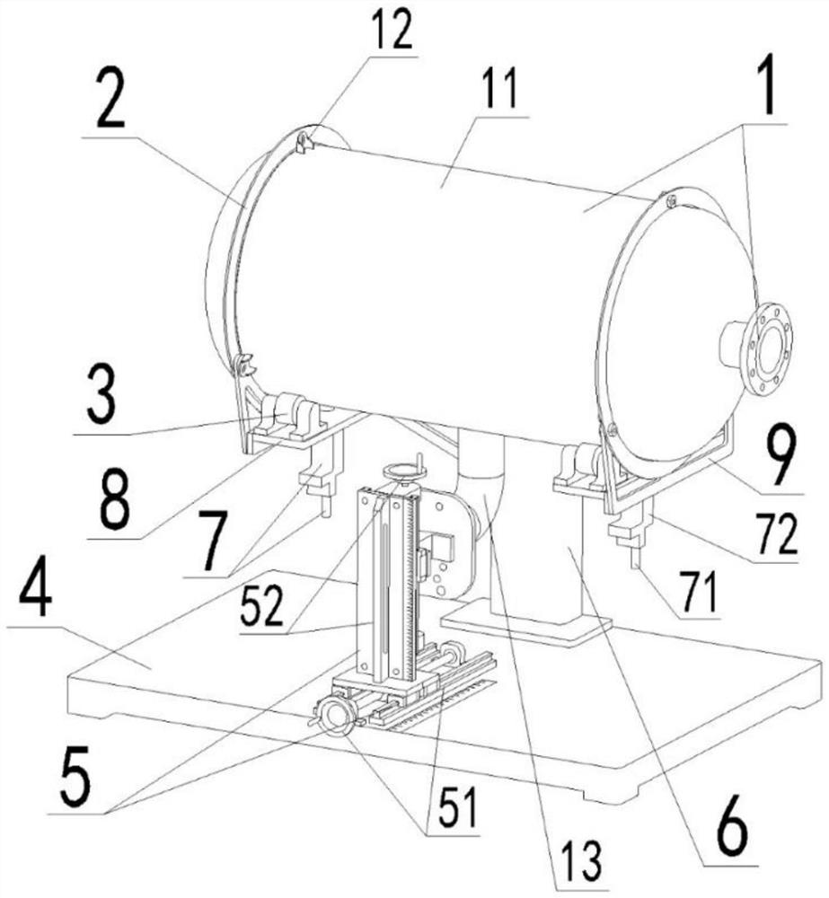
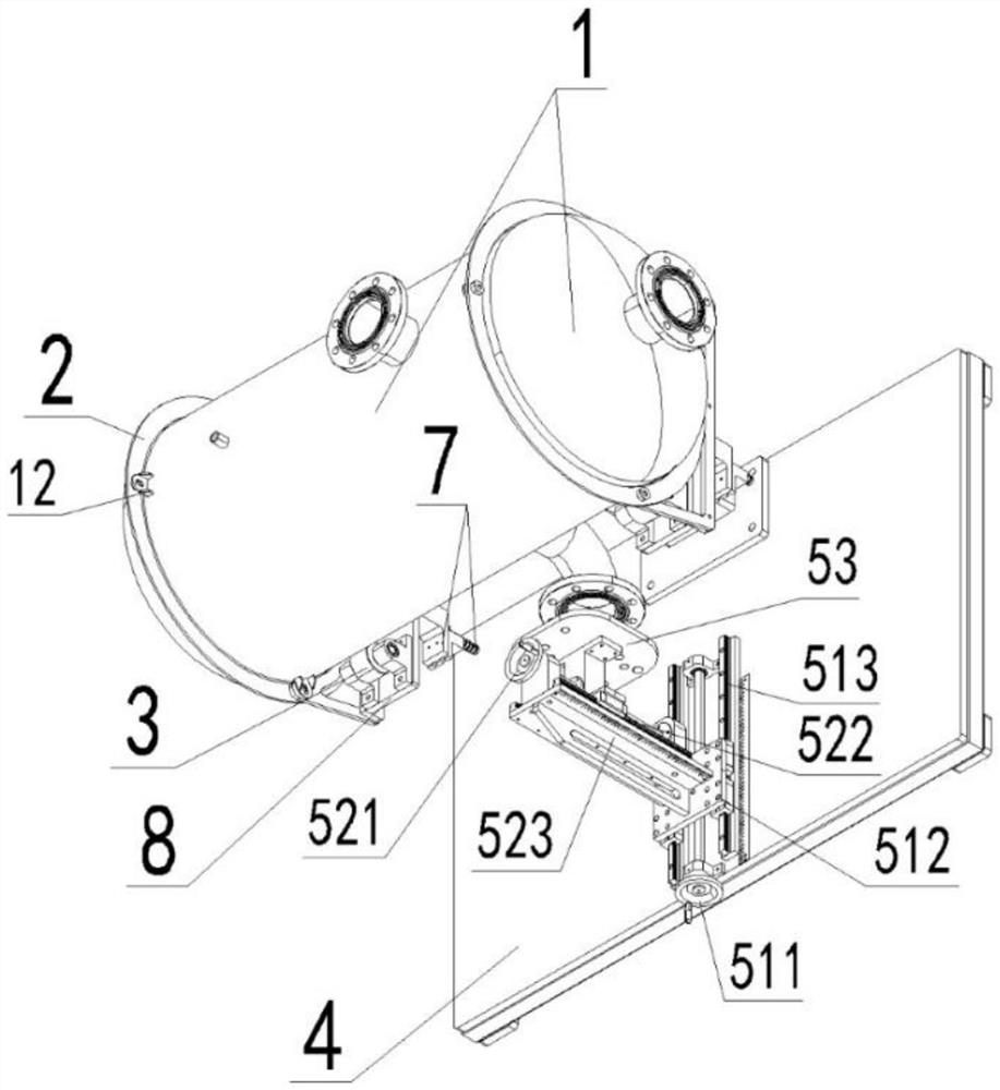
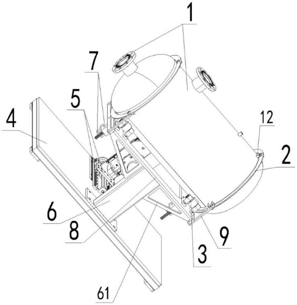
[0050] refer to Figure 1 to Figure 5 , a tank body welding rapid positioning device includes a base 4, and a supporting base 6 arranged on the base 4, a horizontal pallet 8 is arranged on the supporting base 6, and a joist 61 is provided on the lower part of the horizontal pallet 8, and the joist 61 It is in the shape of a right-angled triangle. The upper top surface of the joist 61 is connected to the lower bottom surface of the horizontal pallet 8, and the outer surface of the joist 61 is connected to the outer side of the support seat 6. The joist 61 can make the horizontal pallet 8 and the support seat 6 Good connection stability (such as image 3 and Figure 4 shown), also includes:

[0051] The wheel support assemblies 3 on the left and right sides above the horizontal pallet 8 are arranged. The wheel support assemblies 3 have two groups, and the two groups of wheel support assemblies 3 are symmetrical along the longitudinal vertical center plane of the horizontal pal...


PUM


Abstract

The invention discloses a tank welding rapid positioning device which comprises a base and a supporting seat arranged on the base, a transverse supporting table is arranged on the supporting seat, a supporting beam is arranged on the lower portion of the transverse supporting table, the upper top face of the supporting beam is connected with the lower bottom face of the transverse supporting table, and the outer side face of the supporting beam is connected with the outer side of the supporting seat. The joist enables the connection stability of the transverse supporting table and the supporting seat to be good, wheel supporting assemblies are arranged on the left side and the right side of the upper face of the transverse supporting table, the wheel supporting assemblies are symmetrical along the longitudinal perpendicular center face of the transverse supporting table, the wheel supporting assemblies can stably clamp and support a tank assembly to be welded, and a conical positioning assembly is installed on the bottom face of the transverse supporting table on the lower portions of the wheel supporting assemblies in a penetrating mode. And the conical positioning assembly can perform centering positioning and circumferentially fix the tank body. The positioning device solves the problems of low positioning speed, high cost and low production efficiency in the welding process of the tank assembly special for the water supply equipment with specific small space and unstable water demand, and is suitable for being popularized and used as a matched device for welding when the tank assembly is produced in batches.

Description

technical field [0001] The invention relates to the technical field of a quick positioning device for tank body welding, in particular to a quick positioning device for tank body welding. Background technique [0002] At present, when the water supply equipment is actually used, if the water demand is unstable in a specific small space, it is necessary to use tank components that can match the water supply equipment. During the welding and manufacturing process of the tank body assembly, parts corresponding to the tank body need to be welded and fixed on the tank body. However, the existing tank welding positioning device has the problems of slow tank component positioning speed, high cost and low production efficiency, which cannot meet the actual needs of batch welding and manufacturing tank component products. [0003] Therefore, there is an urgent need for a tank welding rapid positioning device that can match the welding and manufacturing of tank components for water s...

Claims


Application Information

Patent Timeline
IPC IPC(8): B23K37/04B23K101/12
CPCB23K37/0443B23K2101/125
Inventor 邓帮武李广宏邓卓志张孝伟沈亮亮李东潘军周凯
Owner ANHUI SHUNYU WATER AFFAIRS CO LTD
Learn More