

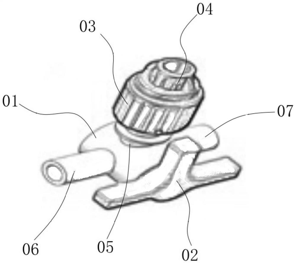
Three-way valve body automatic assembly method and three-way valve automatic assembly line
An automatic assembly, three-way valve body technology, applied in metal processing, metal processing equipment, manufacturing tools, etc., can solve the problems of difficult control of positioning jig position matching accuracy, complex positioning jig conveying structure, and unfavorable assembly accuracy. Achieve the effect of reducing control difficulty, ensuring efficiency and uniformity, and improving processing efficiency
- Summary
- Abstract
- Description
- Claims
- Application Information
AI Technical Summary
Problems solved by technology
Method used
Image

Examples
Embodiment 1
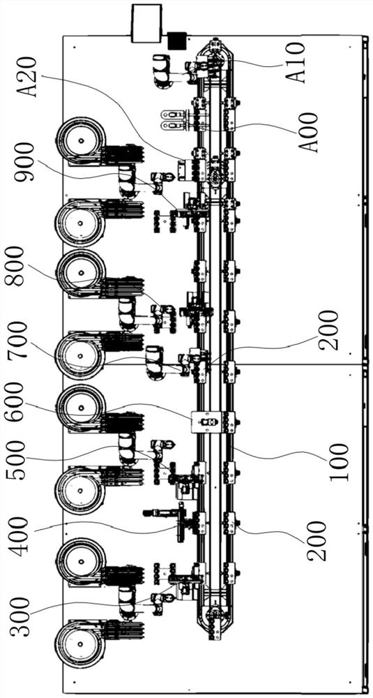
[0055] The automatic assembly method of the three-way valve body disclosed by the present invention is described below in conjunction with the accompanying drawings, and the automatic assembly of the three-way valve body is carried out through an automatic assembly line, as shown in the attached figure 2 As shown, the automatic assembly line includes a conveying line 100, and the conveying line 100 is used to convey the workpiece positioning jig 200. The conveying line 100 can be various known feasible structures, such as those disclosed in the application numbers 202010707635.0 and 201821056077.0 structure shown; or the conveying line 100 may be a turntable structure.
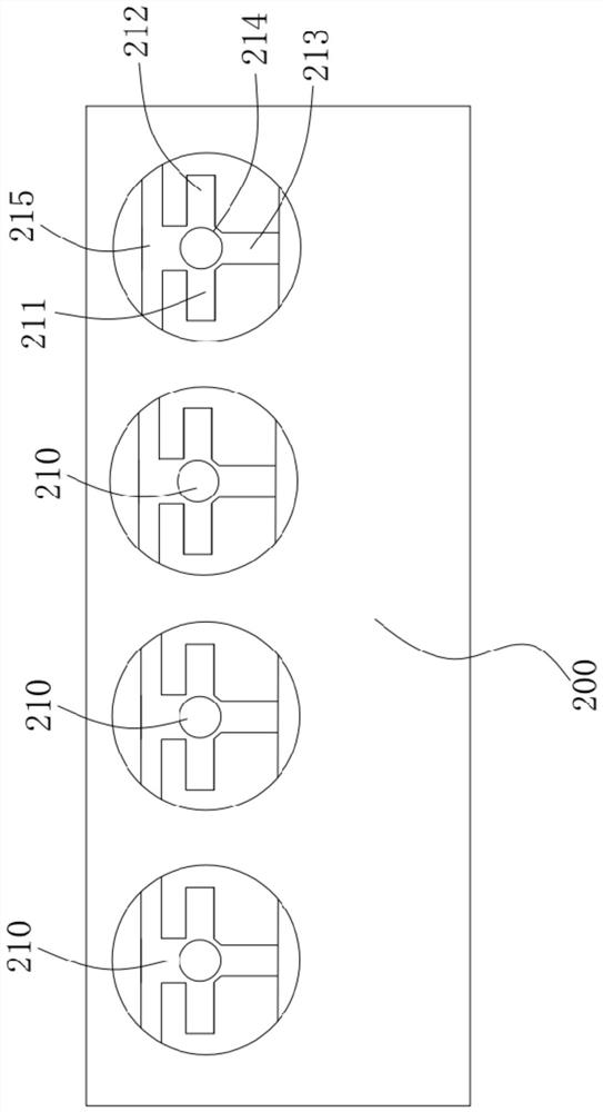
[0056] as attached figure 2 As shown, the workpiece positioning jig 200 is set on the chain conveyor, and the workpiece positioning jig 200 is used for placing and positioning products. as attached image 3 As shown, the top surface of the workpiece positioning jig 200 is formed with a "dry"-shaped positio...
Embodiment 2
[0080] The overall structure of this embodiment is the same as that of the above-mentioned embodiment, the difference is that: figure 2 As shown, the conveying line 100 is an endless conveying line 100, and more preferably, the endless conveying line 100 is waist-shaped, and a group of circular conveying lines are set at equal intervals on the endless conveying line 100 and driven by the endless conveying line 100 to rotate The workpiece positioning fixture 200, the circular conveyor line 100 includes a chain drive mechanism, the workpiece positioning fixture 200 is connected to the driving chain of the circular conveyor line 100, and the workpiece positioning fixture 200 is rolled on the waist-shaped track , so that when the drive chain of the chain drive mechanism rotates, it drives a set of workpiece positioning jigs 200 to rotate. When the conveying line 100 stops conveying, a group of workpiece positioning fixtures 200 on the conveying line 100 can be connected with the ...
Embodiment 3
[0085] This embodiment is further designed on the basis of the structure and process of the above-mentioned embodiments as follows: that is, in the above-mentioned S4, during pressing, it is detected in real time whether the pressing height of the pressing mechanism meets the requirements; when the pressing height meets the requirements, the In the above S5, the turning mechanism turns over the workpiece on the workpiece positioning fixture 200; when the pressing height does not meet the requirements, in the above S5, the turning mechanism removes the workpiece from the workpiece positioning fixture 200, and When the workpiece positioning jig 200 moves to the second assembly mechanism 800 , the third assembly mechanism 900 , and the detection mechanism A00 , none of them operate. In this way, the assembly quality can be effectively guaranteed, and unnecessary subsequent assembly can be reduced at the same time, which is beneficial to energy saving, and at the same time facilita...
PUM
 Abstract
Description
Claims
Application Information