Compressor

A technology for compressors and connecting pipes, applied in the field of compressors, can solve the problems of single installation form, limited application scope, complex variable structure, etc., and achieve the effects of convenient use, convenient and flexible application

Pending Publication Date: 2022-03-22
韩帅杰
View PDF0 Cites 0 Cited by
  • Summary
  • Abstract
  • Description
  • Claims
  • Application Information

AI Technical Summary

Problems solved by technology

[0003] Linear compressors are mainly reciprocating piston compressors. The current compressors have a single structure and a single installation form, and the variable structure is relatively complicated, and the scope of application is limited.

Method used


Image

  • Compressor
  • Compressor

Examples


Embodiment

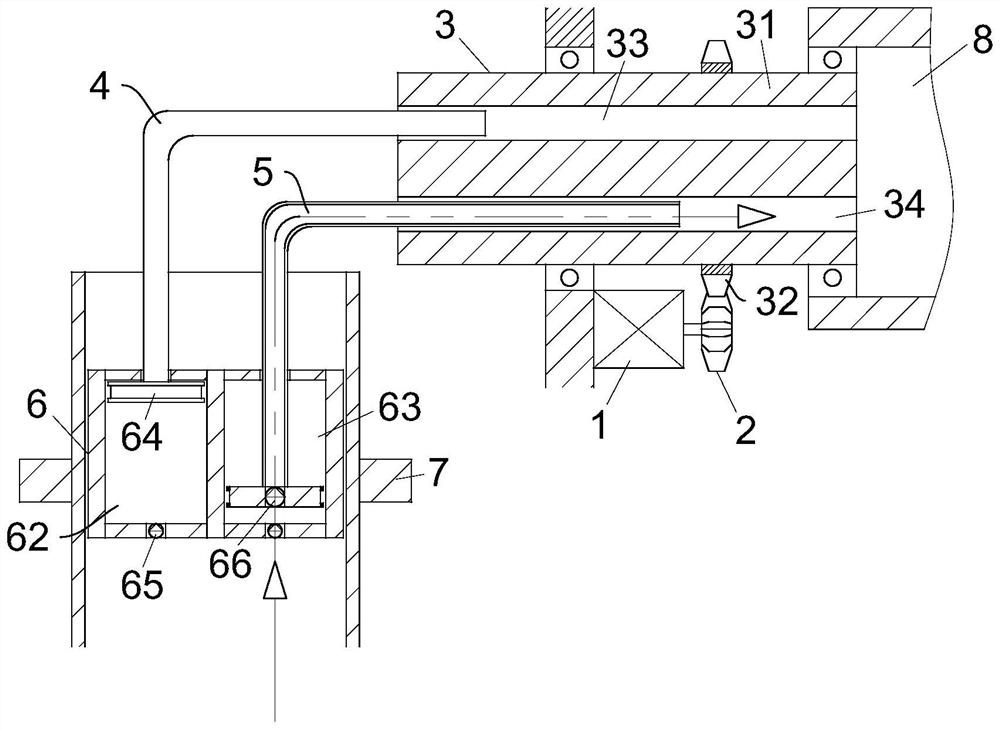
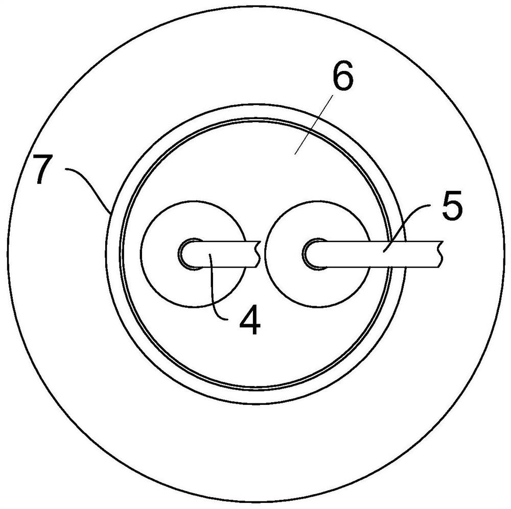
[0023] refer to figure 1 and figure 2 , a compressor, comprising a motor 1, the motor 1 is connected to a gear 2, the gear 2 meshes with a rotating column 3, the right end of the rotating column 3 is rotatably connected to a storage chamber 8, and the left end of the rotating column 3 is slidably connected to at least one first connecting pipe 4 and at least one first connecting pipe 4 Two connecting pipes 5, the two ends of the first connecting pipe 4 and the second connecting pipe 5 communicate with the inner pumping cylinder 6 and the storage chamber 8 respectively, and the inner pumping cylinder 6 rotates on the mounting seat 7; the inner pumping cylinder 6 is provided with The first pumping chamber 62 and the second pumping chamber 63 correspond to the number of the first connecting pipe 4 and the second connecting pipe 5 and communicate with each other. Both the first pumping chamber 62 and the second pumping chamber 63 are slidingly sealed. Connect the piston 64, the ...

Embodiment approach

[0025] As an embodiment of the present invention, the rotating column 3 includes a rotating column main body 31, and a ring gear 32 is fixed outside the rotating column main body 31, and the ring gear 32 meshes with the gear 2. The rotating column main body 31 is provided with a first sliding ventilation groove 33 and The second sliding ventilation groove 34 , the first connecting pipe 4 and the second connecting pipe 5 are sealed and slidably inserted into the first sliding ventilation groove 33 and the second sliding ventilation groove 34 respectively.

[0026] As an embodiment of the present invention, the number of the first connecting pipe 4 and the second connecting pipe 5 is an even number, which ensures the stress stability of the internal pumping cylinder 6 as a whole when the piston 64 moves.

[0027] As an embodiment of the present invention, the cylinder body of the inner pumping cylinder 6 is equipped with a regulating valve for communicating the first pumping cham...


PUM


Abstract

The invention relates to the technical field of compressors, in particular to a compressor which comprises a motor, a motor connecting gear and a gear meshing rotary column, the left end of the rotary column is slidably connected with at least one first connecting pipe and at least one second connecting pipe, and the two ends of the first connecting pipe and the two ends of the second connecting pipe communicate with an inner suction air cylinder and a storage cavity correspondingly. The inner suction cylinder is rotationally arranged on the mounting seat; first air exhaust chambers and second air exhaust chambers which correspond to the first connecting pipes and the second connecting pipes in number and are communicated with the first connecting pipes and the second connecting pipes in number are arranged in the inner air exhaust cylinder, pistons are connected in the first air exhaust chambers and the second air exhaust chambers in a sliding and sealing mode, and the pistons are connected with the first connecting pipes and the second connecting pipes in a sealing mode; first one-way valves are arranged at the bottom ends of the first air exhaust chamber and the second air exhaust chamber; second one-way valves are arranged in the centers of the two pistons; the first one-way valve and the second one-way valve are communicated equally. The bending angles of the first connecting pipe and the second connecting pipe can be changed according to different application scenes, and the device is more convenient and flexible to use.

Description

technical field [0001] The invention relates to the technical field of compressors, in particular to a compressor. Background technique [0002] A compressor is a driven fluid machine that elevates low-pressure gas to high-pressure gas, and is the heart of the refrigeration system. It inhales low-temperature and low-pressure refrigerant gas from the suction pipe, drives the piston to compress it through the operation of the motor, and discharges high-temperature and high-pressure refrigerant gas to the exhaust pipe to provide power for the refrigeration cycle. In this way, the refrigeration cycle of compression→condensation (heat release)→expansion→evaporation (heat absorption) is realized. Compressors are divided into piston compressors, screw compressors, centrifugal compressors, linear compressors, etc. [0003] Linear compressors are mainly reciprocating piston compressors. The current compressors have a single structure and a single installation form, and the variable...

Claims


Application Information

Patent Timeline
Patent Type & Authority Applications(China)
IPC IPC(8): F04B35/04F04B39/12F04B39/00F04B39/10F04B49/22
CPCF04B35/04F04B39/123F04B39/00F04B39/1033F04B49/225
Inventor 韩帅杰黄伟健
Owner 韩帅杰
Why Eureka
Try Eureka