
Gas tank with high safety

A gas tank and safety technology, applied in the field of gas tanks, can solve the problems of inconvenient movement, heavy gas tank, damage to the side wall of the gas tank, etc., and achieve the effects of reducing the risk of explosion, better use effect and good protection effect

Pending Publication Date: 2022-03-22
刘飞飞
View PDF0 Cites 0 Cited by
  • Summary
  • Abstract
  • Description
  • Claims
  • Application Information

AI Technical Summary

Problems solved by technology

However, the gas tank used outdoors is unstable and may fall over, and the gas tank is heavy and inconvenient to move. Bumping may occur during the moving process. Dumping and bumping will cause serious damage to the side wall of the gas tank. It may even cause an explosion, which is relatively dangerous. The current gas tank internal cavity is a whole to place gas. When a fire occurs in the gas tank during use, the combustion can only be stopped after all the gas is burned. A large amount of gas is generated during continuous combustion The hot gas may cause the explosion of the gas tank, which is very dangerous. Therefore, a gas tank with higher safety is proposed

Method used


Image

  • Gas tank with high safety
  • Gas tank with high safety
  • Gas tank with high safety

Examples


Embodiment Construction

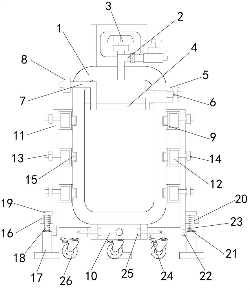
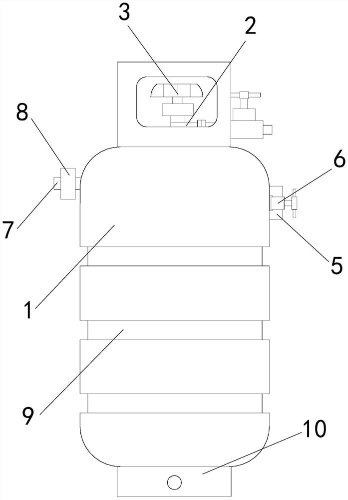
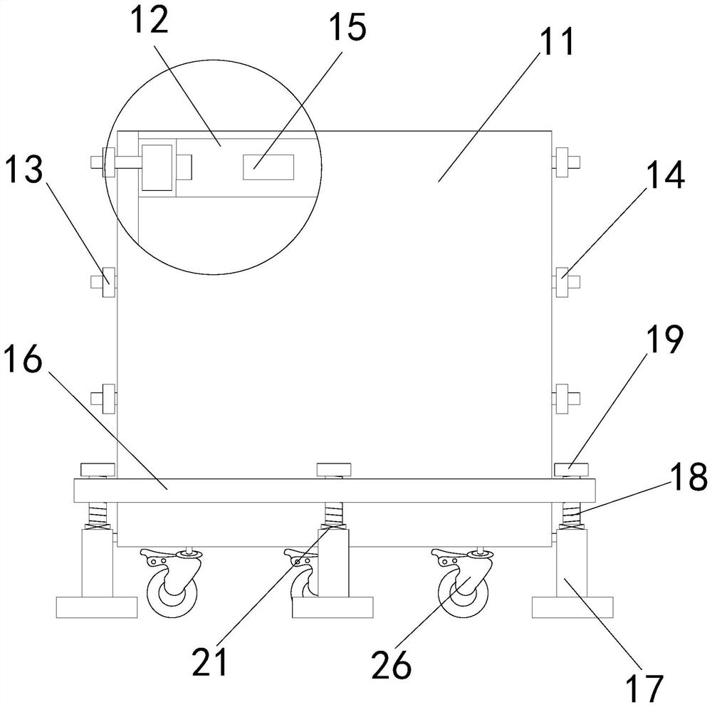
[0022] Such as figure 1 As shown, a gas tank with high safety is invented, which includes a gas tank body 1, a partition mechanism arranged inside the gas tank body, and a protection mechanism arranged outside the gas tank body.

[0023] Specifically, such as figure 1 As shown, the separation mechanism includes a partition 4, an air outlet pipe 2 and a first valve 3, the gas outlet pipe 2 is provided in the middle of the outer upper end of the gas tank body 1, the first valve 3 is provided in the middle of the outlet pipe 2, and the gas tank body 1 The upper end of the interior is horizontally fixed with a partition 4, and the right side of the upper end of the partition 4 is provided with an air-introducing pipe 5. The lower end of the air-introducing pipe 5 passes through the partition 4 and extends to the lower end of the partition 4, and the middle part of the air-introducing pipe 5 passes through the gas tank. The right wall of the body 1 extends to the outer end of the ...


PUM


Abstract

The invention relates to the technical field of gas tank preparation, in particular to a high-safety gas tank which reduces damage and effectively prevents explosion and comprises a gas tank body and a protective sleeve, a gas outlet pipe is arranged at the upper end of the gas tank body, a partition plate is arranged at the upper end of the interior of the gas tank body, a gas guide pipe is arranged on the right side of the upper end of the partition plate, and a gas inlet pipe is arranged on the left side of the upper end of the partition plate. An annular groove is formed in the side wall of the outer end of the gas tank body, a tubular base is arranged at the lower end of the gas tank body, an inflation fixing ring is arranged in the protective sleeve, a clamping block is arranged on the inner wall of the inflation fixing ring, universal wheels are arranged on the front side, the rear side, the left side and the right side of the lower wall of the protective sleeve, and an adjusting fixing ring is arranged at the lower end of the side wall of the protective sleeve. Stable bottom supports are arranged on the front, back, left and right sides of the lower end of the adjusting fixing ring, an adjusting screw is arranged in the middle of the upper end of each stable bottom support, an adjusting through hole is formed in the adjusting fixing ring, the upper end of each adjusting screw penetrates through the corresponding adjusting through hole and is provided with a rotating block, a connecting through hole is formed in the middle of the lower wall of the protective sleeve, and a bolt is arranged on the inner wall of the connecting through hole.

Description

technical field [0001] The invention relates to the technical field of gas tank equipment, in particular to a gas tank with high safety. Background technique [0002] Gas tank (liquefied petroleum gas cylinder) is a steel cylinder for storing gas. The wall thickness of the steel cylinder is about 2.5 mm, the internal pressure is 0.5-1.2 MPa, and the safe use period is 15 years. Regular inspection is required every four years. With the continuous improvement of people's living standards, many families like to go to the wild for camping, barbecue and other activities. Cooking, cooking and barbecue all need to use gas tanks. However, the gas tank used outdoors is unstable and may fall over, and the gas tank is heavy and inconvenient to move. Bumping may occur during the moving process. Dumping and bumping will cause serious damage to the side wall of the gas tank. It may even cause an explosion, which is relatively dangerous. The current gas tank internal cavity is a whole to ...

Claims


Application Information

Patent Timeline
IPC IPC(8): F17C13/08F17C13/12
CPCF17C13/08F17C13/085F17C13/12
Inventor 刘飞飞
Owner 刘飞飞
Learn More