FCEV (Fuel Cell Electric Vehicle) hydrogen fuel installation unit electric-control initiative hydrogen discharging system

An installation unit and hydrogen fuel technology, applied in the automotive field, can solve the problems of unfavorable driving safety, difficult emission, and high hydrogen pressure, and achieve the effects of being beneficial to driving safety, reducing the risk of explosion, and reducing use.

Pending Publication Date: 2018-08-03
XIHUA UNIV
View PDF12 Cites 11 Cited by
  • Summary
  • Abstract
  • Description
  • Claims
  • Application Information

AI Technical Summary

Problems solved by technology

[0003] But it is precisely because hydrogen is used as fuel that it has to face the ensuing problems, such as the high-pressure hydrogen storage tank used to store hydrogen is heated or in high temperature weather, or the hydrogen storage tank is damaged due to impact. When the pressure in the tank suddenly rises or even leaks, there are safety risks such as combustion and explosion. However, the hydrogen in the hydrogen storage tank is high in pressure and concentration, and it is not easy to discharge directly to the atmosphere. The reason is that if a large amount of hydrogen encounters an open flame in the atmosphere Prone to explosion, not conducive to driving safety

Method used


Image

  • FCEV (Fuel Cell Electric Vehicle) hydrogen fuel installation unit electric-control initiative hydrogen discharging system
  • FCEV (Fuel Cell Electric Vehicle) hydrogen fuel installation unit electric-control initiative hydrogen discharging system
  • FCEV (Fuel Cell Electric Vehicle) hydrogen fuel installation unit electric-control initiative hydrogen discharging system

Examples


Embodiment Construction

[0031] The present invention will be further described below in conjunction with the accompanying drawings.

[0032] It should be noted that words such as "first", "second", "third" and "fourth" are often used in the present invention, which are only for the convenience of description and understanding of the present invention, and do not constitute a claim against the present invention. Invention Limitations.

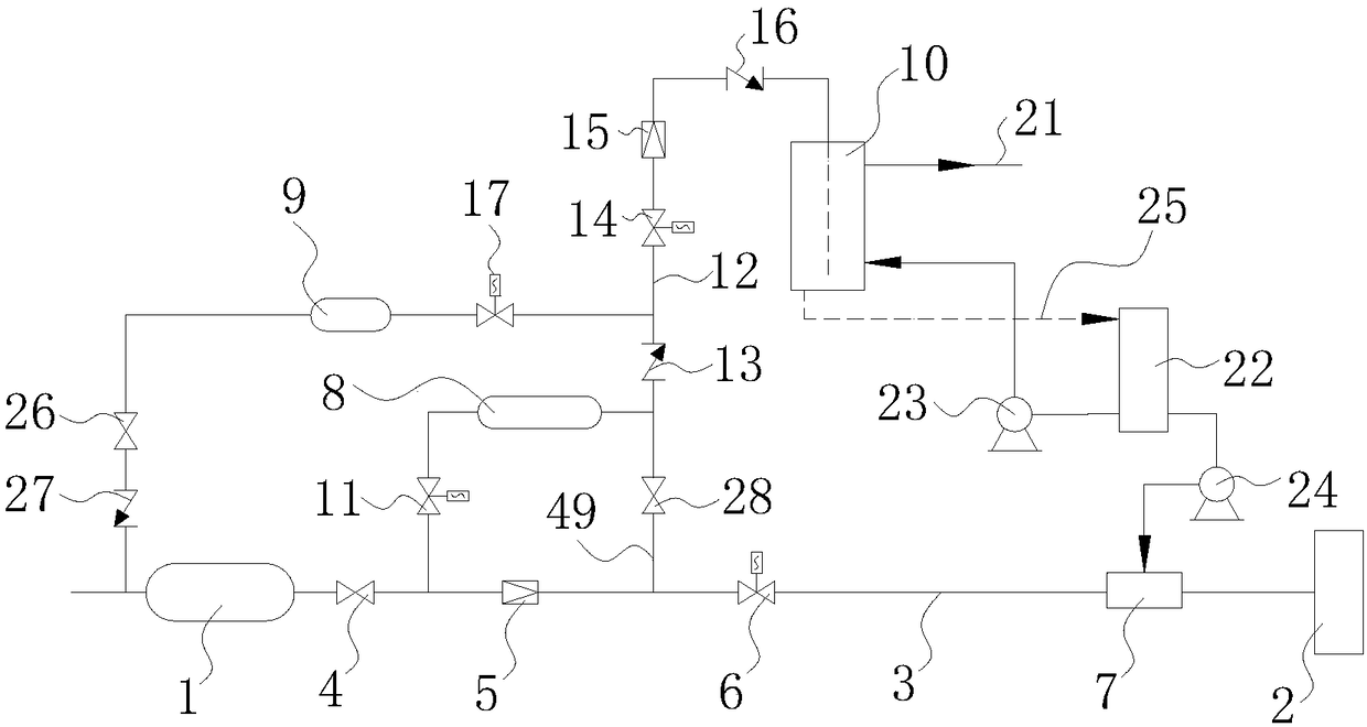
[0033] Such as figure 1 with figure 2 As shown, it includes an electronic control unit ECU41, an explosion-proof hydrogen storage device 1 for storing hydrogen, a fuel cell 2 and a hydrogen exhaust device for exhaust and pressure relief. The explosion-proof hydrogen storage device 1 is connected to the fuel through a hydrogen supply pipeline 3 The battery 2 is connected to supply hydrogen to the fuel cell 2 , and the hydrogen supply pipeline 3 is provided with a first regulating valve 4 , a first pressure reducing valve 5 , a first electromagnetic valve 6 and a humi...


PUM


Abstract

The invention relates to the technical field of fuel cell cars, and aims at providing a safe and explosion-proof hydrogen fuel installation unit electric-control initiative hydrogen discharging system. According to a technical scheme, the FCEV (Fuel Cell Electric Vehicle) hydrogen fuel installation unit electric-control initiative hydrogen discharging system comprises an electric control unit ECU,an explosion-proof hydrogen storage apparatus, a fuel cell and a hydrogen discharging apparatus, the hydrogen discharging apparatus comprises a buffer tank, a nitrogen tank, a water trough and an exhausting pipe, a branch pipe which is arranged on a hydrogen supply pipeline between the explosion-proof hydrogen storage apparatus and the fuel cell is connected with one end of the buffer tank, the branch pipe is provided with a second electromagnetic valve, and the other end of the buffer tank is separately connected with the water trough and the hydrogen supply pipeline by virtue of the hydrogen discharging pipeline and a reflux pipeline. One end of the nitrogen tank is connected to the hydrogen discharging pipeline by virtue of a pipeline, a pipeline adopted by the hydrogen supply pipelineand the hydrogen discharging pipeline is a pipeline with an expansion structure and comprises a straight pipe section and an expansion section formed by expanding the pipeline, and the expansion section and the straight pipe section are interconnected to form a whole body. The safe and explosion-proof hydrogen fuel installation unit electric-control initiative hydrogen discharging system is convenient in operation, safe and explosion-proof.

Description

technical field [0001] The invention relates to the technical field of automobiles, in particular to an electronically controlled active hydrogen exhaust system of an FCEV hydrogen fuel installation unit. Background technique [0002] FCEV, short for Fuel Cell Electric Vehicle. The hydrogen used as fuel is chemically reacted with the oxygen in the atmosphere in the fuel cell installed in the car, thereby generating electric energy to start the electric motor, and then drive the car. [0003] But it is precisely because hydrogen is used as fuel that it has to face the ensuing problems, such as the high-pressure hydrogen storage tank used to store hydrogen is heated or in high temperature weather, or the hydrogen storage tank is damaged due to impact. When the pressure in the tank suddenly rises or even leaks, there are safety risks such as combustion and explosion. However, the hydrogen in the hydrogen storage tank is high in pressure and concentration, and it is not easy to...

Claims


Application Information

Patent Timeline
Patent Type & Authority Applications(China)
IPC IPC(8): H01M8/0438H01M8/0444H01M8/04746
CPCH01M8/04388H01M8/04447H01M8/04753H01M2250/20Y02E60/50
Inventor 邓鹏毅
Owner XIHUA UNIV
Why Eureka
Try Eureka