Weighing sensor based on automatic adjusting mechanism

A weighing sensor and automatic adjustment technology, which is applied in the field of weighing sensors, can solve problems such as manual maintenance, difficulty in normal work, and poor measurement accuracy of weighing sensors, so as to ensure weighing accuracy, improve disassembly convenience, and improve The effect of job stability

Pending Publication Date: 2022-03-22
安徽天平机械股份有限公司
View PDF0 Cites 0 Cited by
  • Summary
  • Abstract
  • Description
  • Claims
  • Application Information

AI Technical Summary

Problems solved by technology

However, regardless of the fixed beam structure or the simply supported beam structure, as long as it is connected by a screw, it is bound to require a certain pretightening force of the screw. Due to the influence of long-term cyclic stress on the screw, the pretightening force of the screw changes gradually, which eventually leads to elasticity. The connection between the body and the base is loose, and the measurement accuracy of the load cell is deteriorated. Since the load cell is generally installed under the weighing platform, manual maintenance is inconvenient, and it does not have a lifting function after the bolt is loose. It is often difficult to find, resulting in untimely maintenance.
[0003] More importantly, the environmental conditions under the weighing platform are relatively harsh, and the mounting bolts are seriously rusted for a long time. When the sensor is repaired and replaced, the bolts cannot be removed. Usually, the bolts can only be removed by gas cutting, which is time-consuming and expensive. The heat causes the load plate of the scale body to deform, and it is difficult to work normally after the exchange, resulting in a very large exchange error

Method used


Image

  • Weighing sensor based on automatic adjusting mechanism
  • Weighing sensor based on automatic adjusting mechanism
  • Weighing sensor based on automatic adjusting mechanism

Examples


Embodiment 1

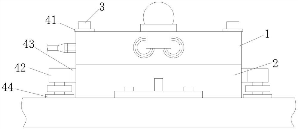
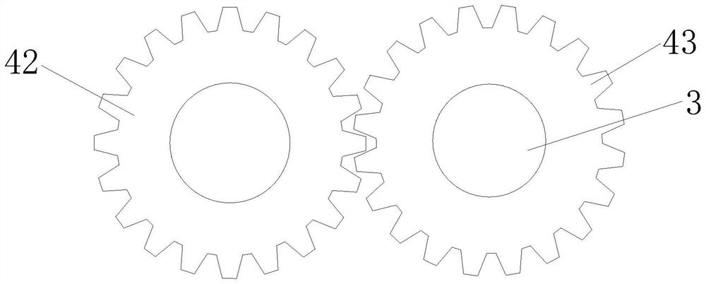
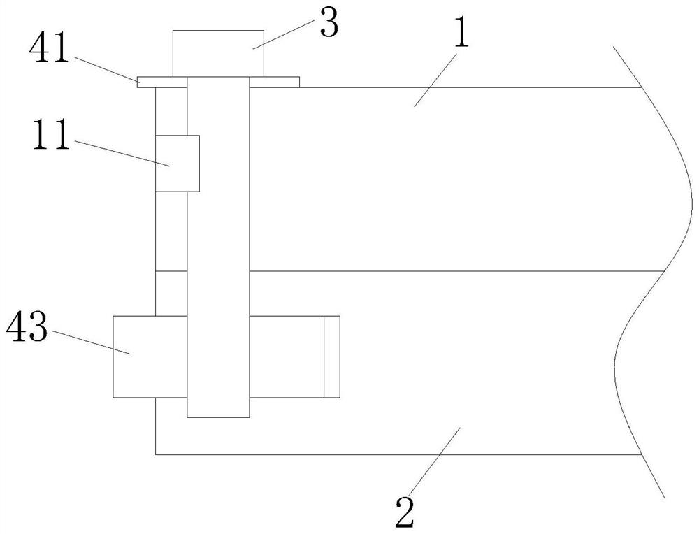
[0018] Embodiment 1, referring to the accompanying drawings, a load cell based on an automatic adjustment mechanism, including an elastic body 1, a base 2, and a bolt 3 threaded on the base 1 after passing through the elastic body 1; also includes an adjustment mechanism; the adjustment mechanism Sensing the tightness of the connection between the elastic body 1 and the base 2, and adjusting the tightness of the connection between the elastic body 1 and the base 2 by driving the bolt 3 to rotate;

[0019] Introduce an adjustment mechanism on the load cell to monitor the tightness of the connection between the elastic body 1 and the base 2, and adjust the connection tightness between the elastic body 1 and the base 2 by driving the bolt 3 to rotate after the elastic body 1 and the base 2 are loosely connected , so that the firmness of the connection between the elastic body 1 and the base 2 is always maintained, avoiding the problem of weighing errors caused by the loose connect...


PUM


Abstract

The invention discloses a weighing sensor based on an automatic adjusting mechanism. The weighing sensor comprises an elastic body, a base and a bolt, wherein the bolt penetrates through the elastic body and then is in threaded connection with the base; the device further comprises an adjusting mechanism. The adjusting mechanism senses the connection tightness degree between the elastic body and the base and drives the bolt to rotate to adjust the connection tightness degree between the elastic body and the base. The adjusting mechanism is introduced on the weighing sensor to monitor the connection tightness between the elastic body and the base, and the connection tightness between the elastic body and the base is adjusted by driving the bolt to rotate after the connection between the elastic body and the base is loosened, so that the connection firmness between the elastic body and the base is always kept; the problem of weighing errors caused by loosening of bolt joints is avoided, and the working stability of the weighing sensor is greatly improved. Furthermore, the whole adjustment process is automatically completed without human participation, so that the elastic body and the base are always kept in certain connection firmness, and the weighing precision is ensured; besides, according to the structure, when the bolt rusts, the motor can drive the gear to drive so that the bolt can be loosened, the problem that the bolt is difficult to disassemble and even can only be cut off due to the fact that the bolt rusts is solved, and disassembling convenience after the bolt rusts is greatly improved.

Description

technical field [0001] The invention relates to the technical field of weighing sensors, in particular to a weighing sensor based on an automatic adjustment mechanism. Background technique [0002] At present, double shear beam load cells are widely used in various electronic weighing equipment such as electronic truck scales and rail scales. The existing double-shear beam sensors all use screws to fix the elastic body of the sensor and the base together, thereby forming a double-end fixed beam structure or a simply supported beam structure. However, regardless of the fixed beam structure or the simply supported beam structure, as long as it is connected by a screw, it is bound to require a certain pretightening force of the screw. Due to the influence of long-term cyclic stress on the screw, the pretightening force of the screw changes gradually, which eventually leads to elasticity. The connection between the body and the base is loose, and the measurement accuracy of the...

Claims


Application Information

Patent Timeline
IPC IPC(8): G01G23/01
CPCG01G23/01
Inventor 张班本黄青松王成张兴汪振全
Owner 安徽天平机械股份有限公司
Why Eureka
Try Eureka