Metal plate welding clamp

A technology for welding fixtures and metal sheets, applied in welding equipment, auxiliary welding equipment, metal processing equipment, etc., can solve problems such as inaccurate positioning, unstable clamping, and inconvenient operation, so as to improve production efficiency, reduce welding deformation and Effect of residual stress and labor reduction

Pending Publication Date: 2022-03-25
CENT SOUTH UNIV
View PDF0 Cites 0 Cited by
  • Summary
  • Abstract
  • Description
  • Claims
  • Application Information

AI Technical Summary

Problems solved by technology

Usually, a set of fixtures can only clamp specific workpieces. In the field of fixtures, there are still problems of inaccurate positioning and clamping for butt welding of unequal thickness metal plates and fillet welding of plates with different angles. Problems of instability and inconvenient operation

Method used


Image

  • Metal plate welding clamp
  • Metal plate welding clamp
  • Metal plate welding clamp

Examples


Embodiment Construction

[0039] The specific embodiments of the present invention will be described in further detail below in conjunction with the drawings and specific embodiments. The following examples or drawings are used to illustrate the present invention, but are not used to limit the scope of the present invention.

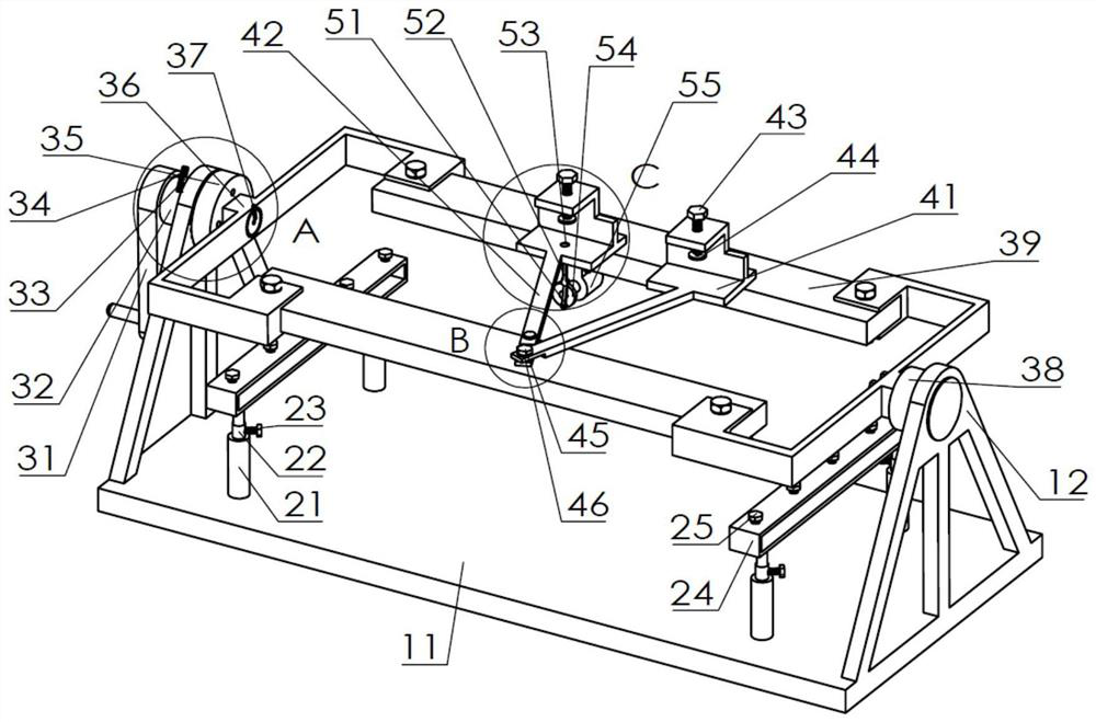
[0040] see Figure 1 to Figure 12 , The invention provides a sheet metal welding fixture, the fixture device mainly includes a weldment support module, a weldment anti-deformation control module, a weldment rotation positioning module, a weldment clamping and fixing module, and a weldment vertical positioning module.

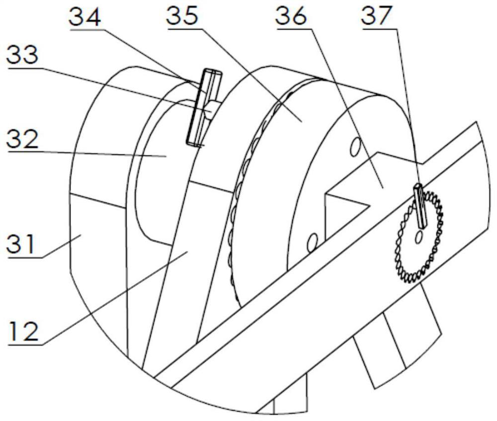
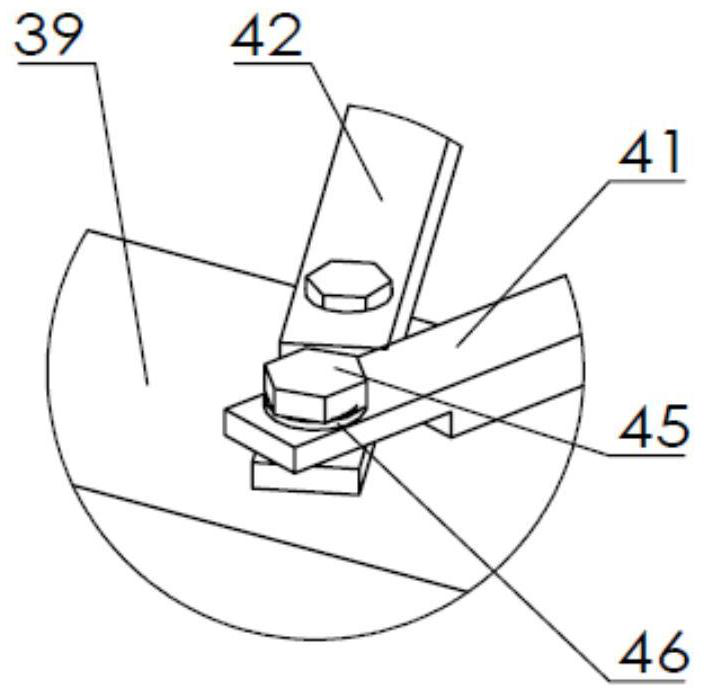
[0041] The weldment support module is composed of a horizontal bottom plate 11 and two side rib plates 12, and equal-diameter through holes are provided on the side rib plates 12 of the clamp body for supporting the shaft 32 and the connecting piece 38, and The left reinforcing rib plate 12 is provided with uniformly distributed and equal-diameter through holes on ...


PUM


Abstract

The invention relates to the field of metal connection forming, in particular to a welding clamp for a metal plate. Comprising a base, a reinforcing rib plate, a clamping frame, a rocker arm, a circumferential positioning connecting piece, a clamping plate, a flat plate, a stepping motor, a slider-crank mechanism, a fixed shaft sleeve and the like. The base is a flat plate, reinforcing rib plates provided with through holes are installed at the two ends of the flat plate in a welded mode, the rocker arm is installed on the shaft through a pin, the shaft is in clearance fit with the holes in the reinforcing rib plates, the circumferential connecting piece is connected with the shaft through bolts, and the left end and the right end of the circumferential positioning connecting piece are each provided with equal-diameter blind holes which are evenly distributed in the circumferential direction. Equal-diameter through holes which are the same as the left side of the circumferential positioning connecting piece and evenly distributed on the circumference are distributed in the side wall of the reinforcing rib plate at the left end, the flat plate driven by the rocker arm rotates, circumferential positioning can be achieved through the positioning rod, and equal-diameter through holes which are the same as the right end of the connecting piece and evenly distributed on the circumference are formed in the clamping plate. The flat plate is reversely driven by the positioning pin to rotate so that the positioning precision of the flat plate can be improved, the flat plate and the clamping plate are connected through bolts, the left welding plate is fixed to the flat plate, the right welding plate relatively moves around the left welding plate, and the stepping motor and the slider-crank mechanism are fixed to the flat plate. When the device is used for welding, butt welding of equal-thickness metal plates, butt welding of unequal-thickness metal plates and angle welding of the metal plates are achieved, welding thermal deformation of the metal plates can be reduced through a reversible deformation method when the metal plates are subjected to butt welding, and the welding angle of the metal plates can be freely adjusted during angle welding.

Description

technical field [0001] The invention relates to the field of metal connection forming, in particular to a metal plate welding fixture. Background technique [0002] Metal plate welding process is widely used in various fields due to its high production efficiency, wide adaptability and material saving, and plays an extremely important role in the production of metal structural parts. On the one hand, today’s welding work often requires repeated hoisting of the workpiece, which is inconvenient for welding and clamping. When welding the reverse side of the workpiece, it is necessary to loosen the workpiece first, turn the workpiece over, and then perform welding after positioning and clamping. Manual operation by welders is required, which not only increases labor intensity, reduces welding efficiency, but also affects the quality of weldments. On the other hand, in the actual welding operation, there are situations where metal plates of unequal thickness are welded. How to u...

Claims


Application Information

Patent Timeline
Patent Type & Authority Applications(China)
IPC IPC(8): B23K37/047
CPCB23K37/047
Inventor 李松柏朱启云朱楚王宇航谷楚
Owner CENT SOUTH UNIV
Why Eureka
Try Eureka