Suspension device, control method thereof, vehicle and engineering machinery

A control method and suspension technology, applied in vehicle components, suspension, elastic suspension, etc., can solve the problems of not indicating the cab and frame, affecting the vibration comfort of the cab, driving safety risks, etc., to improve the vibration The effect of comfort

Inactive Publication Date: 2022-03-25
JIANGSU XCMG CONSTR MASCH RES INST LTD +1
View PDF8 Cites 3 Cited by
  • Summary
  • Abstract
  • Description
  • Claims
  • Application Information

AI Technical Summary

Problems solved by technology

[0003] However, when the vehicle is tilted, turned, braked, accelerated, or the road surface is uneven, the chassis system will tilt and sway from side to side, nod and move back and forth. Due to the elastic characteristics of the cab suspension device, the driving The cabin will tilt and swing left and right, nod and move back and forth along with the chassis system, and even amplify this movement phenomenon, which will seriously affect the vibration comfort of the cab and pose a risk to driving safety.
[0004] The existing patented suspension device with shimmy compensation (CN200980151319.1) mainly includes structures such as locking mechanism, upper bracket, shock absorbing unit, left lower bracket, right lower bracket, and Watt linkage assembly, which can realize cab The relative movement with the frame is only vertical movement or rotation around the middle hole of the hub, and no lateral movement can occur; however, it cannot control the roll of the cab when the vehicle is tilted and the road is uneven, and the cab will follow the chassis to roll , due to the elastic nature of the suspension, the roll situation will be even more severe than that of the chassis
[0005] The existing invention patent is the cab suspension device with swing stabilization mechanism (CN201280065430.0), which mainly includes the chassis, lower cross bridge, upper cross bridge, spring / shock absorber assembly, hydraulic cylinder and other structures, which can well realize the cab suspension The swing stability in various driving conditions can provide active vibration reduction at the same time, allowing limited swing movement of the cab relative to the chassis, but it does not indicate whether the roll of the cab and the frame can be actively adjusted, because it is at a safe angle Considering that the cab and the frame are not expected to roll synchronously in extreme conditions

Method used


Image

  • Suspension device, control method thereof, vehicle and engineering machinery
  • Suspension device, control method thereof, vehicle and engineering machinery
  • Suspension device, control method thereof, vehicle and engineering machinery

Examples


Embodiment 1

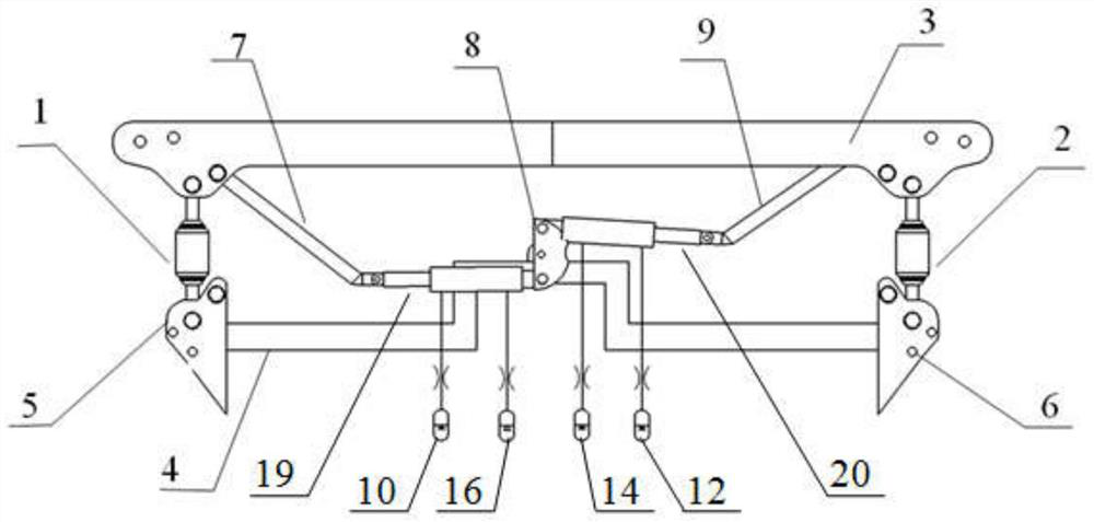
[0044] Such as figure 1 and 2 As shown, the present embodiment provides a suspension device, which includes an upper beam 3, a lower beam 4, a Watt linkage mechanism, an autonomous attitude adjustment system and a vibration damping system.

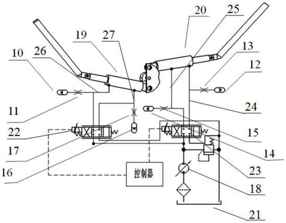
[0045] Such as figure 1 As shown, the Watt linkage mechanism is used to control the left and right swing of the cab, including connecting rod A 7, hydraulic cylinder A19, intermediate connecting rod 8, hydraulic cylinder B 20 and connecting rod B 9, and one end of connecting rod A 7 is connected to the upper beam 3. The other end is connected to the hydraulic cylinder A19, one end of the connecting rod B9 is connected to the upper beam 3, and the other end is connected to the hydraulic cylinder B20, the hydraulic cylinder A19 and the hydraulic cylinder B20 are respectively connected to the upper and lower ends of the middle connecting rod 8, and the middle The connecting rod 8 is connected with the lower beam 4 . The two ends of the low...

Embodiment 2

[0050] This embodiment provides a method for controlling a suspension device, including:

[0051] (1) Cab left and right swing control

[0052] When the vehicle is driving on an uneven road surface, tilting or turning into a forward driving moment, the cab will roll, laterally shift or sway with the left and right tilt of the chassis. The characteristics of the Watt linkage mechanism can reduce the above motions to The vertical movement of the cab relative to the chassis and the rotation around the installation point of the middle link, and due to the self-locking effect of the Watt linkage mechanism, the rotation of the cab around the installation point of the middle link will be restricted, so that the cab can follow the left and right of the chassis. Swing is under control. Among them, the damping and stiffness of hydraulic cylinder A and hydraulic cylinder B are more than twice the damping and stiffness of air spring A and air spring B, otherwise the elasticity is too sma...

Embodiment 3

[0060] This embodiment provides a vehicle configured with the suspension device described in Embodiment 1, and the suspension device is controlled by the control method described in Embodiment 2.


PUM


Abstract

The invention discloses a suspension device, a control method of the suspension device, a vehicle and engineering machinery. The suspension device comprises an upper cross beam, a lower cross beam, a watt connecting rod mechanism, an automatic posture adjusting system and a vibration reduction system. One end of a connecting rod A in the Watt connecting rod mechanism is connected with an upper cross beam, the other end of the connecting rod A is connected with a hydraulic cylinder A, one end of a connecting rod B is connected with the upper cross beam, and the other end of the connecting rod B is connected with a hydraulic cylinder B; the posture autonomous adjusting system is connected with the hydraulic cylinder A and the hydraulic cylinder B and used for controlling the hydraulic cylinder A and the hydraulic cylinder B to stretch out and draw back according to the cab inclination angle so as to realize autonomous adjustment of the cab inclination angle; the vibration reduction system is connected with the hydraulic cylinder A and the hydraulic cylinder B and used for adjusting damping and rigidity of the hydraulic cylinder A and the hydraulic cylinder B so as to achieve active vibration reduction of the cab. According to the invention, cab swing stable control, inclination attitude control and active vibration reduction can be realized at the same time, and the vibration comfort of the cab is improved.

Description

technical field [0001] The invention belongs to the technical field of vehicles and construction machinery, and in particular relates to a suspension device and a control method thereof, a vehicle and construction machinery. Background technique [0002] The suspension device of the cab generally includes a shock absorbing structure, an anti-rolling structure, a limiting structure and other connecting components. The main functions of the cab suspension device include: supporting function, bearing the weight of the cab assembly and the occupants, avoiding large relative displacement and guiding the vertical movement relative to the chassis, while ensuring a stable connection with the frame; Vibration function, with good vibration isolation performance, to attenuate uneven road surface and vibration and impact transmitted by suspension and frame during acceleration and braking, avoid low-frequency large shaking and have good vibration comfort. [0003] However, when the vehi...

Claims


Application Information

Patent Timeline
Patent Type & Authority Applications(China)
IPC IPC(8): B62D33/06B62D33/10B60G17/019B60G17/08
CPCB62D33/0608B62D33/10B60G17/019B60G17/08
Inventor 庄超陈太荣张达王敏
Owner JIANGSU XCMG CONSTR MASCH RES INST LTD
Why Eureka
Try Eureka