
Single-shaft winding machine for intelligent electronic product winding

A technology of intelligent electronic products and winding machines, which is applied in the direction of thin material processing, delivery of filamentous materials, transportation and packaging, etc., can solve the problems of knotting and winding of linear equipment, and improve the neatness, The effect of increasing the friction and improving the winding effect

Active Publication Date: 2022-03-25
扬州瑞福智能科技有限公司
View PDF13 Cites 0 Cited by
  • Summary
  • Abstract
  • Description
  • Claims
  • Application Information

AI Technical Summary

Problems solved by technology

[0004] In view of the above situation, in order to overcome the defects of the prior art, the present invention provides a single-axis winding machine for intelligent electronic product winding, which effectively solves the problem that the wire-shaped equipment may be wound at one position, and then causes the wire-shaped equipment to become knotted. question

Method used


Image

  • Single-shaft winding machine for intelligent electronic product winding
  • Single-shaft winding machine for intelligent electronic product winding
  • Single-shaft winding machine for intelligent electronic product winding

Examples


Embodiment 1

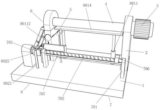
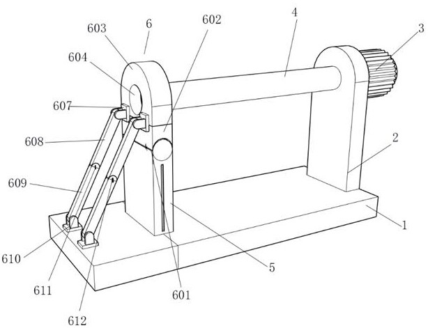
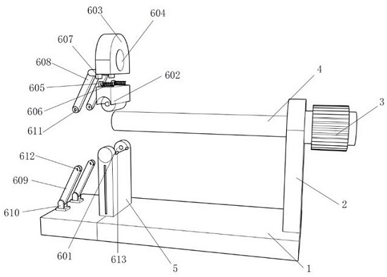
[0031] Embodiment one, by Figure 1-Figure 8 Given, the present invention includes a base 1, the top of the base 1 is equipped with a first side plate 2, one side of the first side plate 2 is rotatably connected with a bobbin 4, and one end of the bobbin 4 is mounted with the output shaft of the first motor 3 , the first motor 3 is fixedly connected to the first side plate 2, the top of the base 1 is also equipped with a second side plate 5, the top of the second side plate 5 is equipped with a discharge assembly 6, and the top of the base 1 is installed with a moving assembly 7 .

Embodiment 2

[0032] Embodiment 2, on the basis of Embodiment 1, the moving assembly 7 includes a first support plate 701 symmetrically installed on the top of the base 1, a moving screw 702 is installed between the two first support plates 701, and one of the first support plates A first contact 703 is installed on one side of 701, a second contact 704 is installed on one side of the other first support plate 701, a second motor 705 is installed on one end of the moving screw 702, and the second motor 705 is fixed to the base 1 Connection, the outer thread of the moving screw 702 is connected with a moving ring 706, one side of the first support plate 701 is installed with an adjustment assembly 8, the bottom end of the moving ring 706 is provided with a limit groove 708, and one side of the moving ring 706 is symmetrically installed with a connection plate 709, the bottom of the connecting plate 709 below is provided with a connecting groove 710, and a rotating roller 711 is symmetrically ...

Embodiment 3

[0034] Embodiment 3, on the basis of Embodiment 2, the adjustment assembly 8 includes an active unit 801 and an adjustment unit 802, wherein the active unit 801 includes a first movable cylinder 8011 symmetrically arranged below the winding shaft 4, the first movable cylinder 8011 and the base 1 Fixed connection, the inside of the first movable cylinder 8011 is equipped with a second spring 8012, the top of the second spring 8012 is equipped with a pressure rod 8013, the pressure rod 8013 is inserted into the inside of the first movable cylinder 8011, and the top of the pressure rod 8013 is installed with Pressing plate 8014, the top of pressing plate 8014 is close to the bottom of bobbin 4, and the front of one of pressing bar 8013 is equipped with connecting rod 8015, and the bottom end of connecting rod 8015 is equipped with mounting plate 8016, and the bottom end of mounting plate 8016 is installed with Bottom rods 8018 and 8108 are plugged into the inside of 8107, and the ...


PUM


Abstract

The invention relates to the technical field of winding equipment, discloses a single-shaft winding machine for winding of intelligent electronic products, and solves the problem that linear equipment is likely to be wound at one position and then knotted, the single-shaft winding machine comprises a base, a first side plate is installed at the top end of the base, one side of the first side plate is rotationally connected with a winding shaft, and the winding shaft is rotationally connected with the winding shaft. An output shaft of a first motor is mounted at one end of the winding shaft, and the first motor is fixedly connected with the first side plate; in the working process, an output shaft of an arranged second motor rotates forwards to drive a movable screw rod to rotate, the bottom end of a movable ring is connected with a limiting strip in a clamped mode, so that the movable ring cannot rotate along with the movable screw rod, the movable ring is driven by the movable screw rod to transversely move, linear equipment penetrates through the position between two rotating rollers, and the linear equipment is driven to rotate. And after the movable ring moves, the linear equipment is driven to move, so that the linear equipment is uniformly wound on the outer side of the winding shaft, and the winding regularity is improved.

Description

technical field [0001] The invention belongs to the technical field of winding equipment, in particular to a single-axis winding machine for winding intelligent electronic products. Background technique [0002] The winding machine is a device that winds a linear object onto a specific workpiece. It is usually used for copper wire winding. The automatic winding machine is a new type that has only been developed in recent years. In order to adapt to high-efficiency and high-yield Requirements, fully automatic models generally adopt multi-head linkage design, the production efficiency of this type is extremely high, greatly reducing the dependence on labor, one operator can take care of several such equipment at the same time, the production quality is relatively stable, very Suitable for processing occasions with high output requirements. [0003] When winding, the wire device may become entangled in one place, which in turn causes the wire device to become knotted, resultin...

Claims


Application Information

Patent Timeline
Patent Type & Authority Applications(China)
IPC IPC(8): B65H54/28B65H54/54B65H67/04
CPCB65H54/2818B65H54/2869B65H54/543B65H67/0411B65H2701/36Y02P70/10
Inventor 高俊兰
Owner 扬州瑞福智能科技有限公司
Learn More