Lifting device for road construction

A technology of roads and suspension rings, which is applied in transportation and packaging, load suspension components, photovoltaic power generation, etc. It can solve problems such as impact on stacking, safety risks, and heavy objects are easy to swing, so as to improve the damping effect, improve the anti-rolling effect, The effect of increased damping

Active Publication Date: 2022-05-17
河南省祥东交通建设工程有限公司 +1
View PDF13 Cites 1 Cited by
  • Summary
  • Abstract
  • Description
  • Claims
  • Application Information

AI Technical Summary

Problems solved by technology

[0005] The purpose of the present invention is to provide a lifting device for road construction in view of the problems that heavy objects are easy to swing during the lifting process and affect their stacking and have safety risks.

Method used


Image

  • Lifting device for road construction
  • Lifting device for road construction
  • Lifting device for road construction

Examples


Embodiment 1

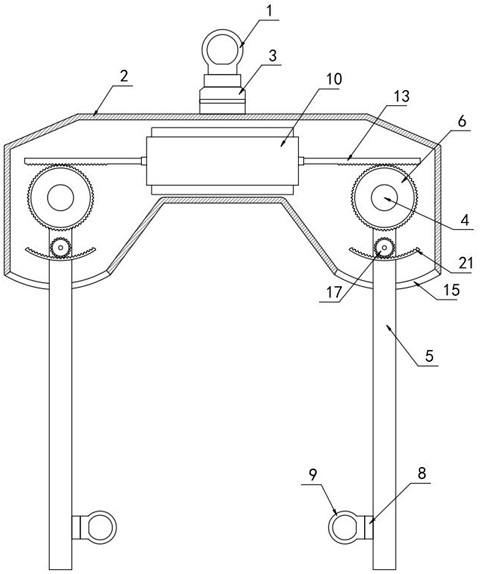
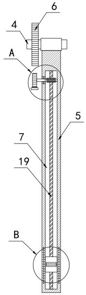
[0029] Such as Figure 1-5 As shown, a lifting device for highway construction includes a lifting ring 1 and a mounting seat 2, a bearing seat 3 is fixedly connected to the mounting seat 2, the lower end of the lifting ring 1 is connected to the bearing seat 3, the mounting seat 2 adopts a hollow structure, and the mounting seat 2 The inner rotating connection has two rotating shafts 4 that are symmetrical about the midline, and the two rotating shafts 4 are fixedly connected with booms 5, and multiple sets of equidistantly arranged booms 5 can be installed on the rotating shafts 4, so as to facilitate counterweight The object is hoisted stably, and the two rotating shafts 4 are fixedly connected with the first gear 6 coaxial with it, and the first gear 6 is provided with a damping mechanism for stabilizing the boom 5, and the two booms 5 are close to each other The side walls of the two chute 7 are provided with a chute 7, the chute 7 is slidingly fitted with a slider 8, the ...

Embodiment 2

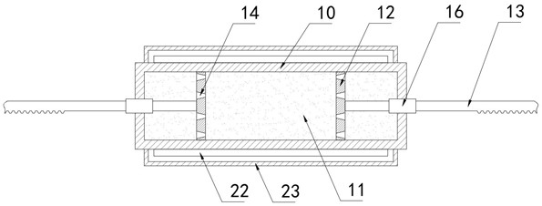
[0040] Such as figure 2 with 5 As shown, the difference between this embodiment and Embodiment 1 is that multiple groups of conductive coils 24 are embedded in the boom 5, the winding direction of the conductive coils 24 extends along the axial direction of the screw rod 19, and the slider 8 is close to the conductive wires. One end of the coil 24 is made of magnetic material. When the slider 8 slides in the chute 7, the conductive coil 24 continuously cuts the magnetic field lines of the slider 8 to generate an induced current.

[0041] Further, two electrode plates 22 are fixedly connected to the side walls of the upper end and the lower end of the damping box 10, and the two electrode plates 22 are arranged facing each other. When the induced current is generated, the two electrode plates 22 can be charged, so that a magnetic field is generated between the two electrode plates 22, and the electrode plate 22 is covered with a shielding cover 23, and the shielding cover 23 ...


PUM


Abstract

The invention belongs to the field of hoisting devices, and in particular relates to a hoisting device for road construction, comprising a suspension ring and a mounting base, the mounting base is fixedly connected with a bearing seat, the lower end of the suspension ring is connected with the bearing housing, and the mounting base Hollow structure is adopted, two rotating shafts symmetrical about the midline are rotationally connected in the mounting seat, and booms are fixedly connected to the two rotating shafts, and coaxial with the two rotating shafts. The first gear of the first gear is provided with a damping mechanism for anti-swing of the boom, and the side walls of the two booms close to each other are provided with slide grooves, and sliding fits are provided in the slide grooves. slider. The present invention makes the damping plate move back and forth in the damping box when the heavy object swings, and the heavy object is stabilized by the damping fluid, and the heavy object is periodically lifted during the swing process, and the kinetic energy is converted into gravitational potential energy for consumption, which can Effectively reduce the swing range of heavy objects until the swing stops completely.

Description

technical field [0001] The invention belongs to the field of lifting devices, in particular to a lifting device for road construction. Background technique [0002] In highway construction, materials, equipment, and operations are the main links to ensure product quality. Among them, lifting devices are indispensable construction equipment, mainly used for handling and stacking construction materials. [0003] After retrieval, the National Patent Publication No. CN102530708B discloses a lifting device, the lifting device includes a suspension ring, the lower end of the suspension ring is connected with a bearing seat, the lower end surface of the bearing seat is fixedly connected with the outer ring of the bearing, and the bearing The center line of the housing is on the same line as the center line of the bearing housing. The inner ring of the bearing is tightly fitted on the journal, and the journal extends downward to the outside of the inner ring. It also includes left...

Claims


Application Information

Patent Timeline
Patent Type & Authority Patents(China)
IPC IPC(8): B66C1/10B66C13/06
CPCB66C1/10B66C13/06Y02E10/50
Inventor 张杰张鹏孙龙李念孟令海李辉
Owner 河南省祥东交通建设工程有限公司
Why Eureka
Try Eureka