Fabricated laminated slab few-support erection construction method

A construction method and technology of laminated slabs, applied to pillars, floors, building components, etc., can solve the impact of construction period, cost and safe and civilized construction, the inability to carry out secondary structure interspersed construction in time, the spacing of vertical poles and the step distance of horizontal poles Minor problems, to achieve the effect of promoting safe and civilized construction, shortening the erection period of the frame, and reducing material input

Pending Publication Date: 2022-03-25
中建科技有限公司华东分公司
View PDF0 Cites 0 Cited by
  • Summary
  • Abstract
  • Description
  • Claims
  • Application Information

AI Technical Summary

Problems solved by technology

However, before the hoisting construction of the laminated slab at this stage, the traditional steel pipe fastener scaffold or quick-release buckle scaffold is still used in the construction of the traditional cast-in-place structure, and it is equipped with sweeping rods, two-way horizontal rods, scissors braces, and adjustable jacking Other structural parts, large amount of materials used, long erection time, and small spacing between vertical poles and horizontal poles, restricting the passage of personnel and material transportation on the construction site, and at the same time affected by the time of dismantling the frame, it is impossible to carry out the secondary structure interspersed in time Construction, which affects the construction period, cost and safe and civilized construction of the project, restricts the promotion of prefabricated buildings

Method used


Image

  • Fabricated laminated slab few-support erection construction method

Examples


Embodiment Construction

[0010] The specific implementation manners of the present invention will be described in detail below in conjunction with the accompanying drawings. The described embodiments are only illustrations and explanations of the present invention, and do not constitute the only limitation of the present invention.

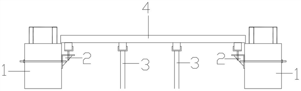
[0011] The construction method of the matching laminated slab with less support of the present invention is as follows: First, fix and position the frame laminated beam 1 by hoisting as required, and reserve a pair of steel corbels 2 for installing the laminated slab bottom support on the laminated beam Pull the bolt holes, set up a single row or double row of independent support frames 3 according to the size of the prefabricated laminated slab 4, adjust the support steel corbel 2 and the independent support frame 3 at the bottom of the slab according to the design elevation and positioning, and then the prefabricated laminated slab 4 can be carried out Hoisting construct...


PUM


Abstract

The invention discloses a few-support erecting construction method for fabricated laminated slabs, and belongs to the technical field of hoisting construction of fabricated building laminated slabs. According to the method, the frame superposed beams are hoisted according to requirements to be fixed and positioned, split bolt holes used for installing the plate bottom supporting steel corbels of the superposed plates are reserved in the superposed beams, single-row or double-row independent supporting frame bodies are erected according to the size of the prefabricated superposed plates, and the plate bottom supporting steel corbels and the independent supporting frame bodies are well adjusted according to the designed elevation and positioning; hoisting construction of the prefabricated laminated slab can be carried out; and plate bottom supporting steel corbels are fixed to the frame superposed beams, independent supporting frame bodies are erected between the superposed beams, the height is adjusted according to design requirements, and after the plate bottom supporting steel corbels and the independent supporting frame bodies are adjusted, the prefabricated superposed plates are hoisted to complete assembly construction. According to the composite slab supporting system, the composite beams and the composite slabs are erected through the rigidity and bearing capacity of the composite beams and the composite slabs, the composite slab supporting system is formed through the slab bottom supporting steel corbels and the independent supporting frame bodies, and the composite slab supporting system which is large in spacing, small in number and high in stability is formed.

Description

technical field [0001] The invention belongs to the technical field of hoisting and construction of prefabricated building composite panels, and in particular relates to a construction method for erecting prefabricated composite panels with few supports. Background technique [0002] With the development of the construction industry, more and more prefabricated buildings are used in office, residential and other building structures. Large-size prefabricated laminated panels are widely used because of their advantages such as high mass production efficiency, convenient hoisting and installation, and no need for slab bottom formwork. However, before the construction of the laminated slab at this stage, the traditional cast-in-place structure is still used in the construction of traditional steel pipe fastener scaffolding or quick-release disc buckle scaffolding, and is equipped with sweeping rods, two-way horizontal rods, scissors braces, and adjustable jacking. Other structu...

Claims


Application Information

Patent Timeline
Patent Type & Authority Applications(China)
IPC IPC(8): E04G25/02E04G21/14E04B5/17
CPCE04G25/02E04G21/14E04B5/17
Inventor 孙小华漆昌勇肖晓董震贺树阳陈琦
Owner 中建科技有限公司华东分公司
Why Eureka
Try Eureka