
Drill rod structure of raise boring machine for hydroelectric system

A technology for raising well drilling rigs and drill pipes, which is applied to drill pipes, drill pipes, drilling equipment, etc., can solve the problems of wasting processing time, wasting materials, and detaching drill pipes, and achieves the effect of increasing stability and reducing obstacles.

Active Publication Date: 2022-03-25
JIANGSU HEXIN PETROLEUM MACHINERY
View PDF21 Cites 0 Cited by
  • Summary
  • Abstract
  • Description
  • Claims
  • Application Information

AI Technical Summary

Problems solved by technology

[0003] In the existing drill pipe structure of the raise drilling rig used in the hydropower system, the drill pipe structure is composed of a circular pipe, which needs to drive the drill pipe to rotate, and the inside of the drill pipe is provided with grooves to facilitate the removal of the drilled sand and stone. When the drilling depth is deep, multiple drill pipes need to be spliced, and the spiral splicing method is used to drive the two drill pipes to be spliced. , one end of the drill hole is stuck, and the other end of the drill pipe is rotated, which will cause the separation between the two drill pipes, which will drive the drill pipe to fall into the inside of the drill hole, and it will be difficult to take out the fallen drill pipe later, resulting in waste of materials , and the problem of wasting processing time

Method used


Image

  • Drill rod structure of raise boring machine for hydroelectric system
  • Drill rod structure of raise boring machine for hydroelectric system
  • Drill rod structure of raise boring machine for hydroelectric system

Examples


Embodiment Construction

[0023] The following will clearly and completely describe the technical solutions in the embodiments of the present invention with reference to the accompanying drawings in the embodiments of the present invention. Obviously, the described embodiments are only some, not all, embodiments of the present invention. Based on the embodiments of the present invention, all other embodiments obtained by persons of ordinary skill in the art without making creative efforts belong to the protection scope of the present invention.

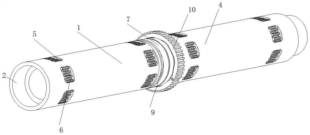
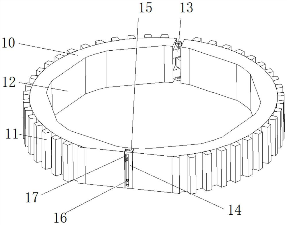
[0024] see figure 1 , figure 2 , image 3 , Figure 4 and Figure 5 , a drill pipe structure of a raise drilling rig for a hydropower system, comprising a first drill pipe 1, a threaded limiting groove 2 is provided inside the first drill pipe 1, and a threaded rod 3 is convenient to drive the first drill pipe 1 on the other side The other side of the first drill rod 1 is fixedly connected with a threaded rod 3, and the threaded rod 3 drives the threaded ...


PUM


Abstract

The invention relates to the technical field of hydroelectric systems, and discloses a raise boring machine drill rod structure for a hydroelectric system, the raise boring machine drill rod structure comprises a first drill rod, one side of the first drill rod is internally provided with a thread limiting groove, and the other side of the first drill rod is fixedly connected with a threaded rod. According to the raise boring machine drill rod structure for the hydroelectric system, by pushing a sealing limiting plate to move to one side and driving a positioning pin to move into the first drill rod, when the first drill rod and the second drill rod are driven to rotate in a threaded mode, hindrance is reduced, and after the first drill rod and the second drill rod are limited in a threaded mode, the sealing limiting plate is pushed, and the first drill rod and the second drill rod are driven to rotate in a threaded mode. After a positioning pin is driven to be movably connected into a groove formed in one side of a second drill rod in a sleeved mode, the position between the first drill rod and the second drill rod can be driven to be limited, the problem that the drill rods loosen and fall off when rotating is avoided, a nut is rotated, the position of a sealing limiting plate is pushed to be limited, and the stability of position limiting of the sealing limiting plate can be improved.

Description

technical field [0001] The invention relates to the technical field of hydropower systems, in particular to a drill pipe structure of a raise drilling rig for a hydropower system. Background technique [0002] In the hydropower system, a raise drilling rig is required to drill holes and drive the raising drilling rig to drill well water. Usually, it is necessary to drive the drill hole to extend underground, but when drilling, it is necessary to use a drill pipe to assist the drilling process. So far, a The utility model relates to a drill pipe structure of a raise drilling rig for a hydropower system. [0003] In the existing drill pipe structure of the raise drilling rig used in the hydropower system, the drill pipe structure is composed of a circular pipe, which needs to drive the drill pipe to rotate, and the inside of the drill pipe is provided with grooves to facilitate the removal of the drilled sand and stone. When the drilling depth is deep, multiple drill pipes ne...

Claims


Application Information

Patent Timeline
Patent Type & Authority Applications(China)
IPC IPC(8): E21B17/043
CPCE21B17/043
Inventor 韩博刘志强荆国业程守业窦斌赵钧羡
Owner JIANGSU HEXIN PETROLEUM MACHINERY
Learn More