Debugging device and debugging method of laser resonant cavity mirror
A resonator and laser technology, which is applied in the field of laser resonator mirror debugging devices, can solve the problems of minimizing the geometric deflection loss of the resonator and low adjustment accuracy, so as to reduce observation errors, improve adjustment accuracy, and improve output performance Effect
- Summary
- Abstract
- Description
- Claims
- Application Information
AI Technical Summary
Problems solved by technology
Method used
Image
Examples
specific Embodiment approach 1
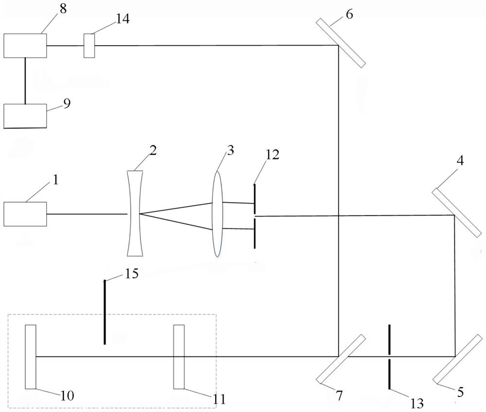
[0025] A laser resonator mirror debugging device, including He-Ne laser 1, negative lens 2, positive lens 3, mirror I4, mirror II5, mirror III6, half mirror 7, CCD camera 8, computer 9 , resonant cavity mirror I10 and resonant cavity mirror II11, the laser light emitted by the He-Ne laser 1 passes through the center of the negative lens 2 and the center of the positive lens 3 in sequence, and is reflected by the reflector I4 to the reflector II5, and then reflected to the Half-mirror 7, the light beam passing through half-mirror 7 is incident on resonant cavity mirror I10 or resonant cavity mirror II11, and said resonant cavity mirror I10 or resonant cavity mirror II11 reflects the incident light beam to the half-transparent mirror 7. The light reflected by the half mirror 7 is reflected by the mirror III 6 to the CCD camera 8 , and the CCD camera 8 is electrically connected to the computer 9 .
[0026] Further, the laser emitted horizontally by the He-Ne laser 1 is perpendicu...
specific Embodiment approach 2
[0038] A debugging method utilizing the debugging device described in Embodiment 1, comprising the following steps:
[0039] S1: Adjust the confocal placement of the negative lens 2 and the positive lens 3 so that the 632.8nm laser emitted by the He-Ne laser 1 passes through the centers of the negative lens 2 and the positive lens 3 in sequence;
[0040] S2: Adjust the position of the pinhole diaphragm I12 so that the aperture is located at the center of the beam;
[0041] S3: Adjust the mirror I4 and mirror II5, and adjust the position of the aperture diaphragm II13, so that the laser passes through the aperture aperture II13 and is horizontally incident on the cavity mirror I10;
[0042] S4: Adjust the resonator mirror I10 so that the incident and reflected 632.8nm laser is irradiated on the pinhole diaphragm II13 and is concentric with the aperture;
[0043] S5: Adjust the half-mirror 7 and mirror III 6 so that the 632.8nm light reflected by the resonator mirror I10 is inc...
PUM
 Abstract
Description
Claims
Application Information
 - R&D
- Intellectual Property
- Life Sciences
- Materials
- Tech Scout
- Unparalleled Data Quality
- Higher Quality Content
- 60% Fewer Hallucinations
Browse by: Latest US Patents, China's latest patents, Technical Efficacy Thesaurus, Application Domain, Technology Topic, Popular Technical Reports.
© 2025 PatSnap. All rights reserved.Legal|Privacy policy|Modern Slavery Act Transparency Statement|Sitemap|About US| Contact US: help@patsnap.com

