Timepiece assembly and manufacturing method thereof

A technology for components, timepieces, used in the field of balance wheels and inertia screws, to manufacture said components, able to solve problems such as stress corrosion of the underlying material, damage to bearing or gripping areas, etc.

Pending Publication Date: 2022-03-25
NIVAROX FAR
View PDF6 Cites 0 Cited by
  • Summary
  • Abstract
  • Description
  • Claims
  • Application Information

AI Technical Summary

Problems solved by technology

Assembling an inertia mass on a balance wheel will cause defects in the protective layer in areas that are exposed to stress during deformation of the arms, and in areas of support or grip where the layer can be locally damaged
The protective layer is then no longer impermeable to aggressive substances such as ammonia or chlorine, which can lead to stress corrosion of the underlying material

Method used


Image

  • Timepiece assembly and manufacturing method thereof
  • Timepiece assembly and manufacturing method thereof
  • Timepiece assembly and manufacturing method thereof

Examples


Embodiment Construction

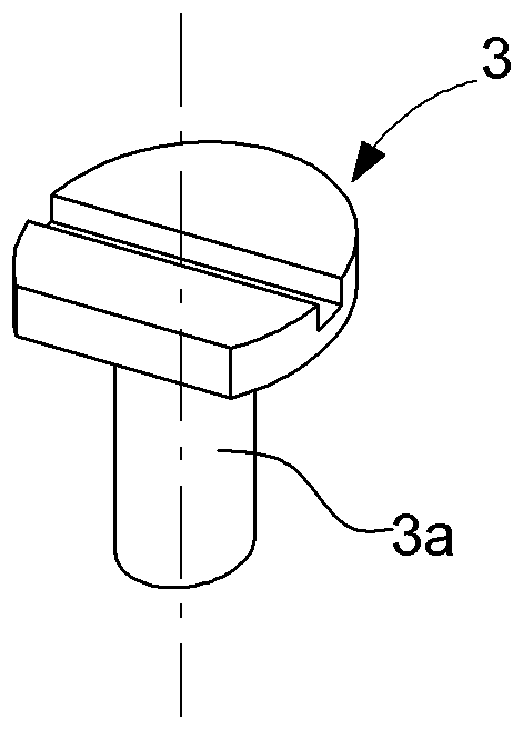
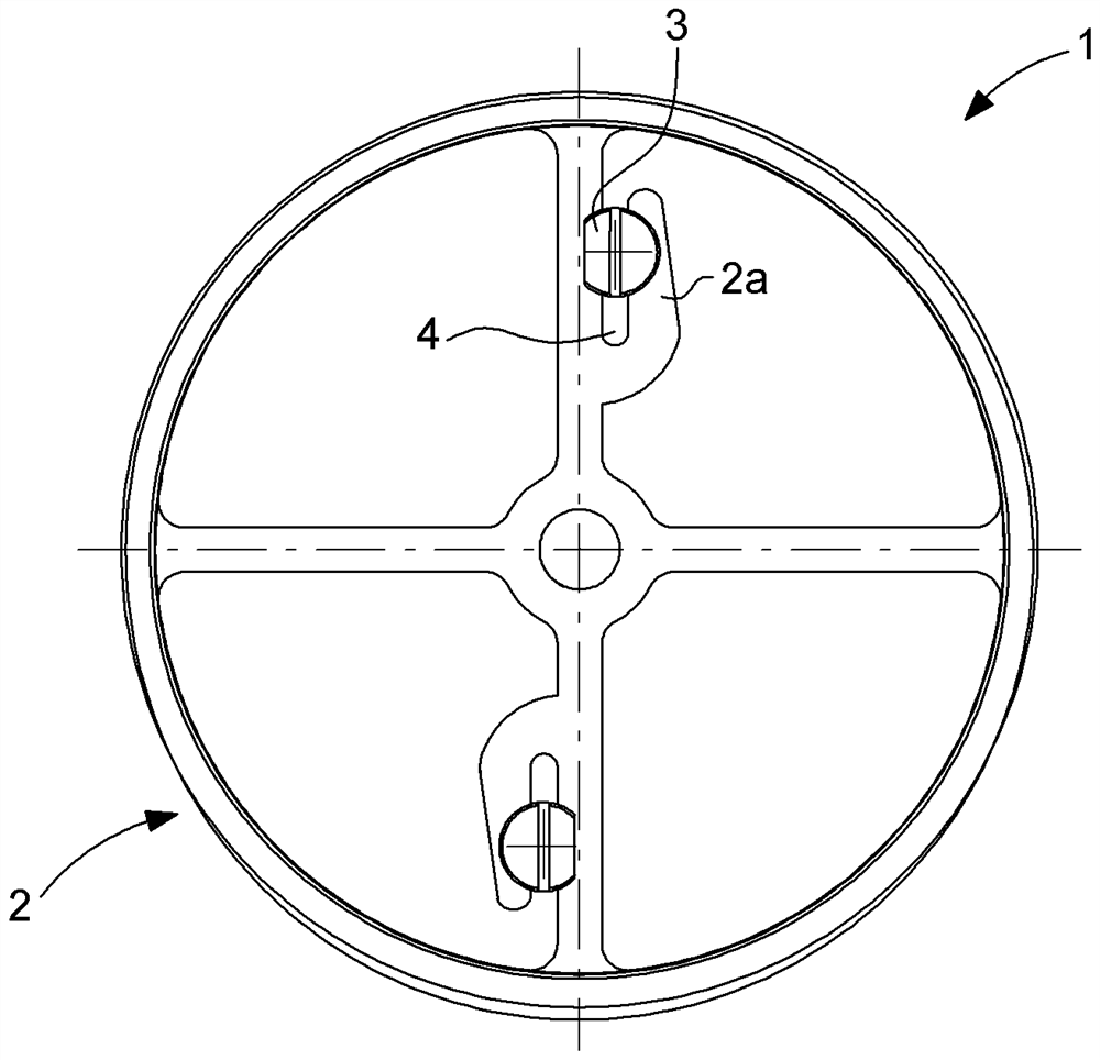
[0014] The invention relates to a timepiece assembly comprising at least two parts assembled under stress. By way of example, as figure 1 , the first part is the balance wheel 2, which includes an elastic arm 2a defining a slot 4 that receives the second part during assembly, the second part being in figure 2 Inertia screw 3 is also visible. It can also be a pressed-in element, such as a shock pin in a plateau or a balance wheel on an axle, etc.

[0015] The components may be made from a material selected from the list including copper, copper alloys such as brass or cupronickel, aluminum, aluminum alloys, titanium, titanium alloys, carbon steel, and ferritic and austenitic stainless steels.

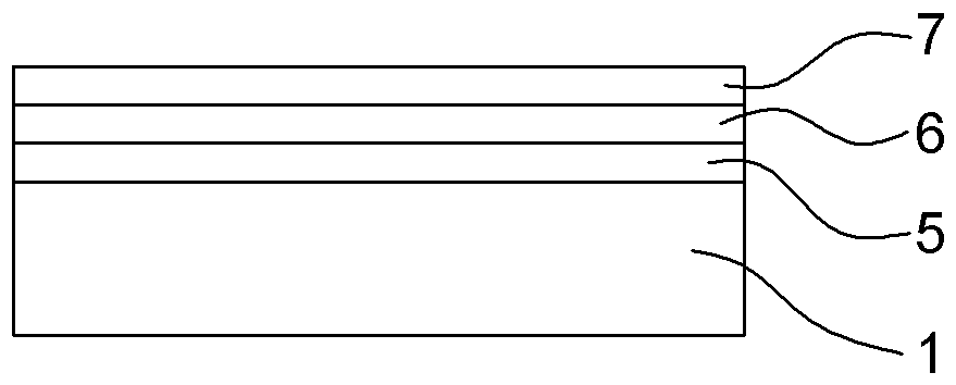
[0016] According to the invention, the timepiece assembly is at least partially coated after assembly with a protective layer intended to cover any defects, such as cracks, incipient cracks, peeling, caused by the assembly process or which may have existed before assembly. Figure 4A...


PUM

PropertyMeasurementUnit
thicknessaaaaaaaaaa
thicknessaaaaaaaaaa

Abstract

Timepiece assemblies and methods of making the same. The invention relates to a timepiece assembly (1) comprising a first part and a second part assembled under stress, characterized in that at least a portion of the surface of the assembly is coated with a protective layer (7) intended to cover defects such as cracks or initial cracks (8) after assembly. The invention also relates to a method for manufacturing the assembly.

Description

technical field [0001] The invention relates to a timepiece assembly comprising two parts assembled under stress, in particular a balance wheel and an inertia screw. The invention also relates to a method for manufacturing said assembly. Background technique [0002] There are many known configurations of balance wheels with means for adjusting the inertia and / or balance of the balance wheel. In particular, there are known balance wheels with an inertia mass, also called an inertia screw, which is screwed or driven into an arrangement in the rim of the balance wheel. Some embodiments have attempted to ensure retention of the inertia screw by clamping. Thus, Swiss Patent No. 705238 discloses a balance comprising at least one groove for receiving the shaft of an inertia screw and clamping it in place; this groove is defined on the one hand by a rigid part of the balance and on the other Aspect is by means of an elastic arm permanently biased towards said rigid part of the b...

Claims


Application Information

Patent Timeline
Patent Type & Authority Applications(China)
IPC IPC(8): G04B17/06C23C28/00
CPCG04B17/06G04B17/063C23C28/00G04B18/006G04B31/06
Inventor J·凡诺德C·查尔邦
Owner NIVAROX FAR
Why Eureka
Try Eureka