Probe for increasing MEMS-OCT scanning imaging field angle
A technology of scanning imaging and field of view, applied in the field of medical machinery, can solve the problem of small scanning field of view of MEMS-OCT probe, and achieve the effect of improving the scanning field of view
- Summary
- Abstract
- Description
- Claims
- Application Information
AI Technical Summary
Problems solved by technology
Method used
Image

Examples
Embodiment 1
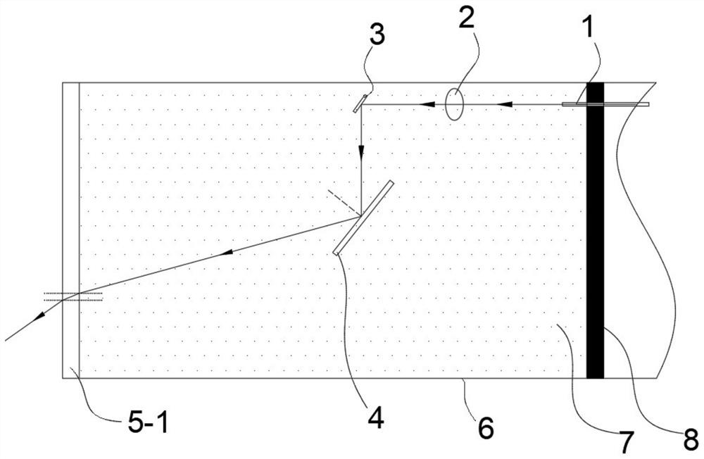
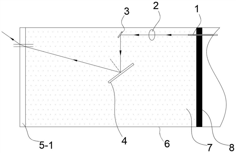
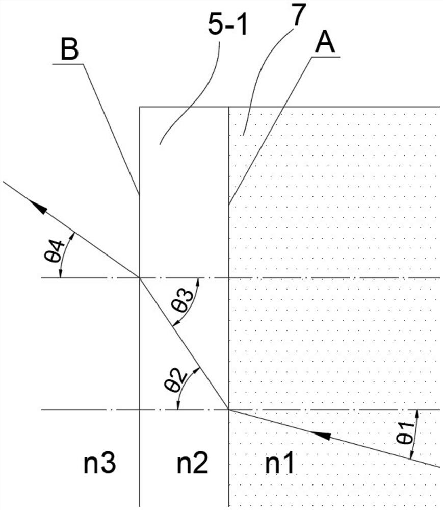
[0037] Such as Figure 1-Figure 4 As shown, a forward-scanning probe that increases the field of view of MEMS-OCT scanning imaging includes an optical fiber 1, a lens 2, a reflective device 3, a MEMS micromirror 4, a first optical window 5-1, and a sealed chamber 6. The cavity 6 is filled with a liquid substance 7, the MEMS micromirror 4 is immersed in the liquid substance 7, the light emitted from the optical fiber 1 passes through the lens 2, the reflective device 3, and the MEMS micromirror 4 in turn, and reaches the first optical window 5- through the liquid substance 7. 1 is shot after refraction.
[0038] Among them, the MEMS micromirror 4 is driven by electrothermal, and its driving method refers to the patent (CN201210363551.5), and the reflective device 3 is a reflector. Liquid substance 7 is a liquid or a mixture of liquid and nanomaterials. The liquid can be one of glycerin (1.4730), mineral oil (1.467), olive oil (1.4763), methyl silicone oil (1.410), indene (1.57...
Embodiment 2
[0054] Such as Figure 5-Figure 8 As shown, a side-scan probe that increases the field of view of MEMS-OCT scanning imaging includes an optical fiber 1, a lens 2, a MEMS micromirror 4, a second optical window 5-2, and a sealed chamber 6. In the sealed chamber 6, Filled with a liquid substance 7, the MEMS micromirror 4 is immersed in the liquid substance 7, the light emitted from the optical fiber 1 passes through the lens 2 and the MEMS micromirror 4 in sequence, and reaches the second optical window 5-2 after being refracted by the liquid substance 7 and then emitted.
[0055] Wherein, the closed chamber 6 is surrounded by the MEMS package body 8 , the side wall and the front end of the side scan probe, and the second optical window 5 - 2 . The optical fiber 1 passes through the MEMS package 8 .
[0056] The specific principle is: the probe is a sealed tube shell filled with a liquid or a mixture of liquid and nanomaterials. The light beam emitted by the optical fiber 1 ent...
Embodiment 3
[0070] Such as Figure 9 , Figure 10 As shown, as a modification of Embodiment 2, the liquid substance 7 in the airtight chamber 6 does not fill the entire chamber, which has the effect of: while increasing the probe field of view, reducing the light passing through the liquid The path length, thereby reducing the absorption of light by the liquid.
PUM
 Abstract
Description
Claims
Application Information
 - R&D
- Intellectual Property
- Life Sciences
- Materials
- Tech Scout
- Unparalleled Data Quality
- Higher Quality Content
- 60% Fewer Hallucinations
Browse by: Latest US Patents, China's latest patents, Technical Efficacy Thesaurus, Application Domain, Technology Topic, Popular Technical Reports.
© 2025 PatSnap. All rights reserved.Legal|Privacy policy|Modern Slavery Act Transparency Statement|Sitemap|About US| Contact US: help@patsnap.com