Static shoulder friction stir welding device and method applied to container side wall splicing
A friction stir and welding device technology, applied in welding equipment, non-electric welding equipment, metal processing equipment, etc., can solve problems such as broken stirring pins, low efficiency of static shoulder friction stir welding, welding failure, etc., to increase fluidity , Improve welding efficiency and reduce the effect of plastic deformation resistance of materials
- Summary
- Abstract
- Description
- Claims
- Application Information
AI Technical Summary
Problems solved by technology
Method used
Image
Examples
Embodiment 1
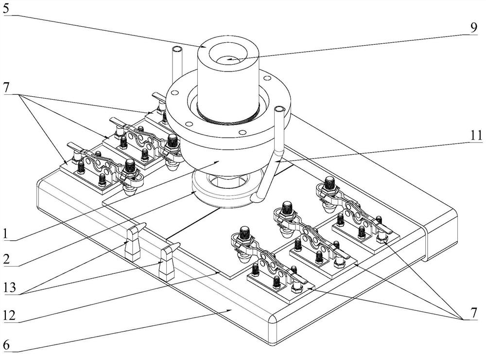
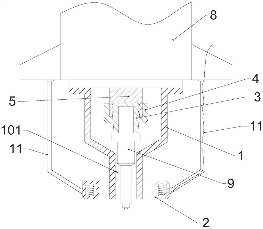
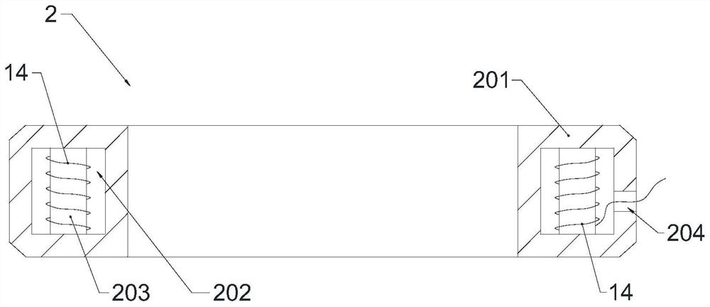
[0027] like Figure 1~Figure 4 The shown static shaft shoulder friction stir welding device applied to the splicing of container side walls includes a drive motor 8, a stirring needle 9 detachably connected to the shaft end of the output shaft 5 of the drive motor 8, and a drive motor housing or a stirring needle 9. The static shaft shoulder 1 fixedly connected to the shell of the welding device, the lower end of the static shaft shoulder 1 is provided with a shaft shoulder hole 101, the lower end of the stirring needle 9 passes through the shaft shoulder hole 101 and protrudes out of the static shaft shoulder 1, and the stirring needle 9 and the shaft shoulder hole 101 There is a gap between the inner walls, a magnetic field vector module 2 is sleeved outside the lower end of the static shaft shoulder 1, the magnetic field vector module 2 is in the shape of a circular ring, and four pairs of heating coils driven by independent power sources are uniformly distributed inside the...
Embodiment 2
[0035] like Figure 1~Figure 4 As shown, the static shoulder friction stir welding method applied to container side wall splicing adopts the static shoulder friction stir welding device applied to container side wall splicing described in Embodiment 1, including the following specific steps:
[0036] S1. Fix the plate 12 to be welded on the telescopic table 6 with the clamping device 7 .
[0037] S2. According to the size of the stirring needle 9 and the thickness of the plate 12 to be welded, adjust the length of the adjustable cable tube bracket 11 and the length of the stirring needle 9 extending from the static shaft shoulder 1, thereby adjusting the position of the magnetic field vector module 2, so that the magnetic field vector The lower end face of the module 2 is flush with the lower end face of the static shaft shoulder 1 .
[0038] S3. Turn on the power supply, start the drive motor, drive the stirring needle 9 to rotate through the output shaft 5 of the drive moto...
PUM
 Abstract
Description
Claims
Application Information
 - R&D
- Intellectual Property
- Life Sciences
- Materials
- Tech Scout
- Unparalleled Data Quality
- Higher Quality Content
- 60% Fewer Hallucinations
Browse by: Latest US Patents, China's latest patents, Technical Efficacy Thesaurus, Application Domain, Technology Topic, Popular Technical Reports.
© 2025 PatSnap. All rights reserved.Legal|Privacy policy|Modern Slavery Act Transparency Statement|Sitemap|About US| Contact US: help@patsnap.com


