Horizontal cantilever long pipe temporary storage frame
A buffer frame and arm length technology, applied in the field of catenary simplified flat wrist arm production, can solve the problems of difficult precise control of processing position, inaccurate positioning, low efficiency, etc., and achieve the effect of improving the degree of automation
- Summary
- Abstract
- Description
- Claims
- Application Information
AI Technical Summary
Problems solved by technology
Method used
Image

Examples
Embodiment 1
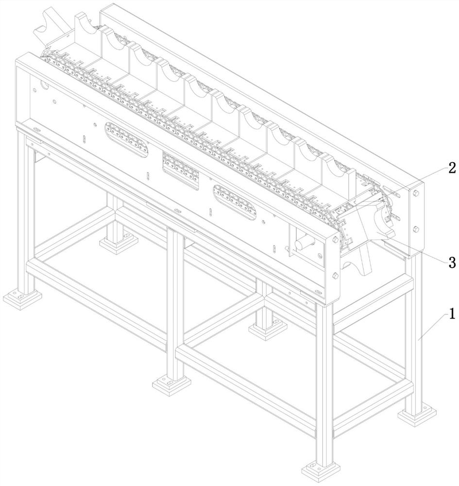
[0023] Refer Figure 1 to 4 As shown, a flat wrist arm long tube buffer, including a support frame 1, which is improved in that the support frame 1 is provided with a turning motion chain 2, and the chain 2 is provided with a plurality of support units. 3, the support unit 3 is circulated under the rope cycle of the rotary motion of the chain 2; the support unit 3 is provided with a support plate 32, and the upper end surface of the support plate 32 is formed downwardly to form an arc surface portion 321. The arc surface portion 321 matches the outer peripheral surface of the long tube.
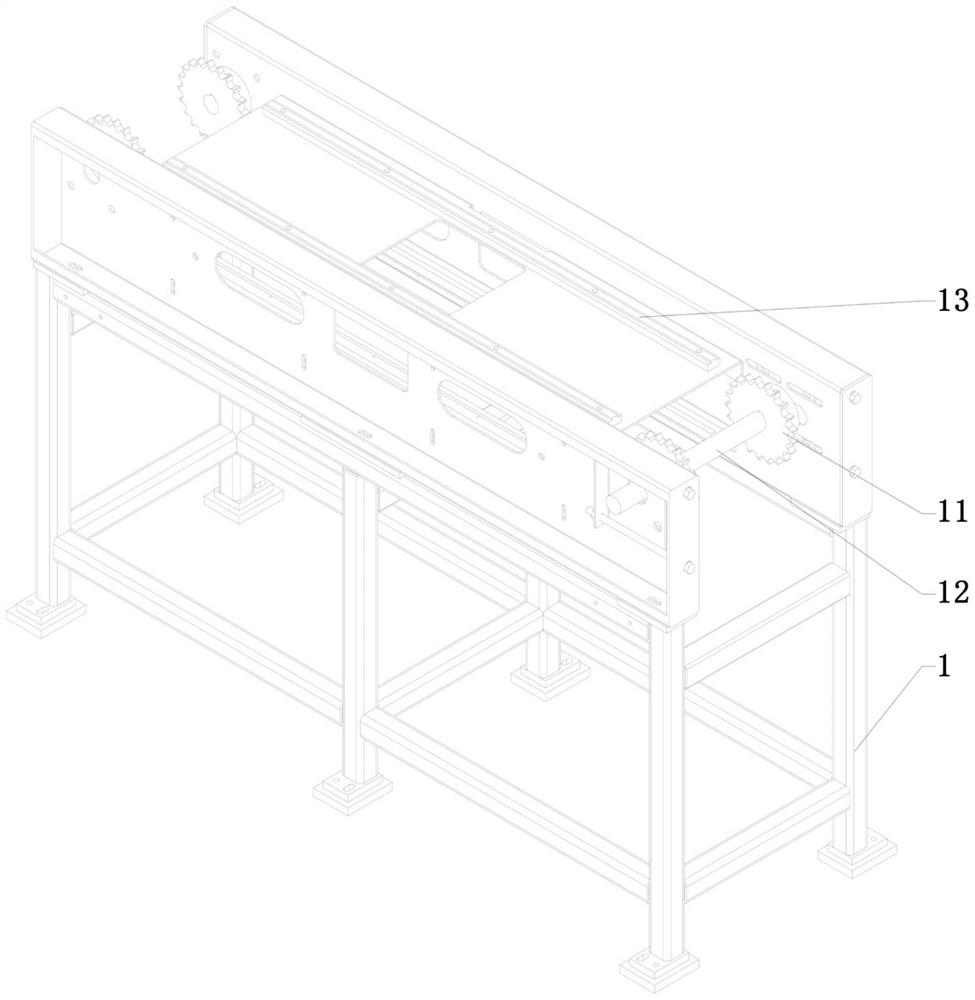
[0024] In this embodiment, the support frame 1 functions as a support, and the chain 2 performs a rotation motion in the drive of the gear 11 and drives the support unit 3 for a ring circulation, the support unit 3 for the alarm The long tube is supported and the continuous supply of the long tube is carried out in the annular cycle, and the support platen 32 is used to support the long tube, the ...
Embodiment 2
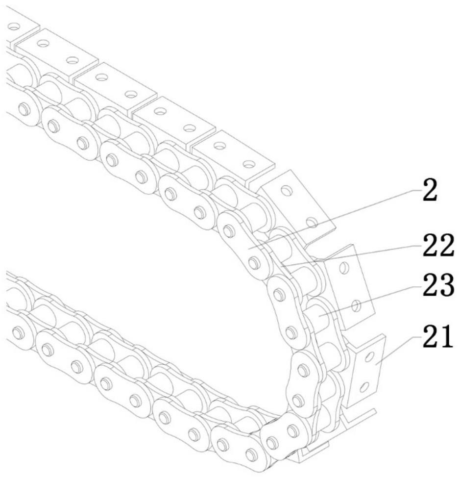
[0033] On the basis of Example 1, reference image 3 As shown, the chain 2 is connected to each other by a plurality of links 22, each of which includes two chains 23, adjacent the adjacent chain column 23 of the adjacent link 12 connects the same connecting angle member 21, The connecting angle member 21 is rotated to each of the chain columns 23, and the chain 2 is connected to each other by a plurality of links 22, each of which includes two chain column 23, two of the same link 22. A chain column 23 is connected to the same connecting angle member 21.
[0034] In this embodiment, the connecting angle member 21 is configured to achieve the connection of the chain 2 and the support unit 3. This embodiment provides two ways of connecting angle members 21 and chain connections. In the first mode, it can be acceded across the link, since the same connecting angle member 21 is connected to the adjacent two-chain column 23 of the adjacent two link 22, the connection angle member 21 an...
Embodiment 3
[0036] On the basis of Example 2, the connecting angle member 21 is an L-shaped, and the vertical portion of the connecting angle member 21 is connected to the chain post 23, the horizontal portion of the connecting angle member 21 and the support. The unit 3 is connected.
[0037] In the present embodiment, the L-shaped connecting angle member 21 is convenient for both the connection angle member 21 and the link 22, facilitating the connection of the angle member 21 and the support unit 3, thereby facilitating the connection of the support unit 3 and the chain 2. And the replacement and maintenance of the support unit 3.
[0038] Further, the support unit 3 further includes a connecting table 31, the connection table plate 31 being coupled to the horizontal portion of the connecting angle member 21, and the support plate 32 is disposed on the connecting table 31.
[0039] In the present embodiment, the arrangement of the connection plate 31 facilitates the connection of the suppo...
PUM
 Abstract
Description
Claims
Application Information