
Power distribution and utilization control system based on IT power distribution system

A control system and power distribution system technology, applied in the direction of electrical components, circuit devices, etc., can solve problems such as failures, secondary disasters, and fundamentally preventing electric leakage and electric shock accidents, so as to eliminate potential safety hazards and improve safety Effect

Pending Publication Date: 2022-03-29
广东荣文科技集团有限公司
View PDF0 Cites 0 Cited by
  • Summary
  • Abstract
  • Description
  • Claims
  • Application Information

AI Technical Summary

Problems solved by technology

[0002] In related technologies, the municipal smart and safe power consumption system has the following problems when using electricity: First, it is impossible to monitor the insulation status of the line in real time, and it cannot be timely and effectively monitored when there is a leakage fault in the line that endangers personal safety Therefore, it is impossible to effectively eliminate the hidden danger of electric leakage in time; second, when electric leakage and electric shock accidents occur in the circuit, the leakage protection switch in the control line can only be in the off state to avoid the expansion of the hazards of electric leakage and electric shock accidents. It cannot fundamentally prevent the occurrence of electric leakage and electric shock accidents; third, the control and protection parameters of the distribution box are set rigidly, and cannot flexibly adapt to complex and changeable load lines; fourth, when a partial fault causes the overall power failure, it cannot operate with a fault , if it cannot be repaired in time, it is easy to cause secondary disasters

Method used


Image

  • Power distribution and utilization control system based on IT power distribution system
  • Power distribution and utilization control system based on IT power distribution system
  • Power distribution and utilization control system based on IT power distribution system

Examples


Embodiment Construction

[0036] Embodiments of the present invention are described in detail below, examples of which are shown in the drawings, wherein the same or similar reference numerals designate the same or similar elements or elements having the same or similar functions throughout. The embodiments described below by referring to the figures are exemplary only for explaining the present invention and should not be construed as limiting the present invention.

[0037] In the description of the present invention, it should be understood that the orientation descriptions, such as up, down, front, back, left, right, etc. indicated orientations or positional relationships are based on the orientations or positional relationships shown in the drawings, and are only In order to facilitate the description of the present invention and simplify the description, it does not indicate or imply that the device or element referred to must have a specific orientation, be constructed and operated in a specific ...


PUM


Abstract

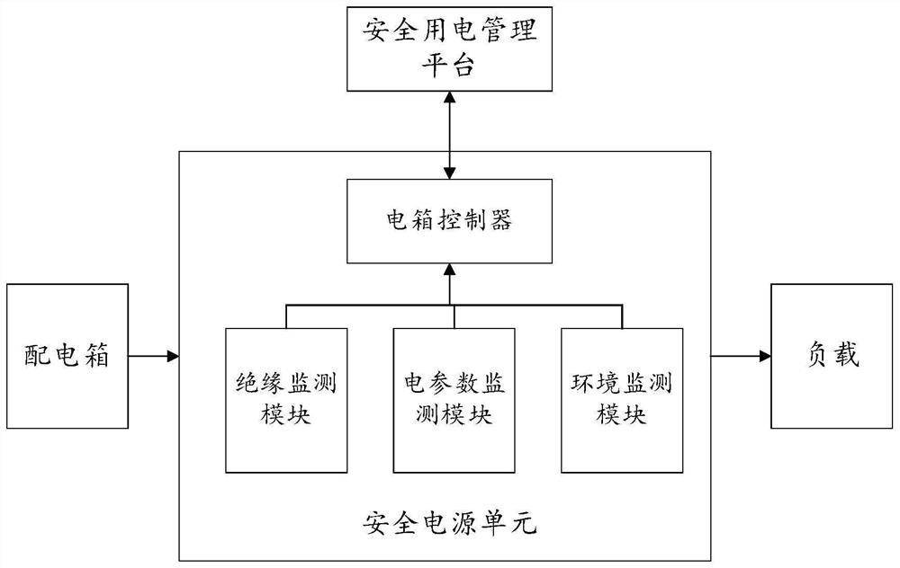
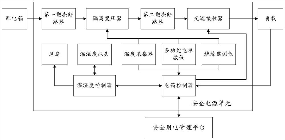
The invention discloses a power distribution and power utilization control system based on an IT power distribution system, which can be applied to the technical field of power utilization safety. According to the invention, the safe power utilization unit is additionally arranged between the distribution box and the load; an insulation monitoring module used for monitoring insulation resistance and stray capacitance of a circuit in the safe power supply unit, an electric parameter monitoring module used for monitoring output electric parameters of the safe power supply unit, and an environment monitoring module used for monitoring working environment parameters in the safe power supply unit are arranged in the safe power utilization unit; when the power distribution system works, the working state of the circuit can be detected in real time, and when the circuit breaks down, the working state of each functional module in the circuit can be controlled through the electric box controller arranged in the safe power utilization unit, so that the function of finding and eliminating potential safety hazards in time is achieved. And meanwhile, the safe power utilization unit and the safe power utilization management platform are wirelessly interacted, so that a worker can timely know the working state of the power distribution system.

Description

technical field [0001] The invention relates to the technical field of electricity safety, in particular to a control system for electricity distribution and electricity consumption based on an IT power distribution system. Background technique [0002] In related technologies, the municipal smart and safe power consumption system has the following problems when using electricity: First, it is impossible to monitor the insulation status of the line in real time, and it cannot be timely and effectively monitored when there is a leakage fault in the line that endangers personal safety Therefore, it is impossible to effectively eliminate the hidden danger of electric leakage in time; second, when electric leakage and electric shock accidents occur in the circuit, the leakage protection switch in the control line can only be in the off state to avoid the expansion of the hazards of electric leakage and electric shock accidents. It cannot fundamentally prevent the occurrence of e...

Claims


Application Information

Patent Timeline
IPC IPC(8): H02J13/00
CPCH02J13/00002H02J13/00032H02J13/00001
Inventor 李志雄李养民赵亮李雄广黄清禹勇强
Owner 广东荣文科技集团有限公司
Learn More