Film bulk acoustic resonator, manufacturing method thereof and filter
A thin-film bulk acoustic wave and resonator technology, applied in electrical components, impedance networks, etc., can solve the problems of radio frequency systems that cannot meet high performance, the quality factor cannot be further improved, and the structural strength is not enough, so as to eliminate boundary clutter and suppress Effect of shear wave loss and improvement of mechanical strength
- Summary
- Abstract
- Description
- Claims
- Application Information
AI Technical Summary
Problems solved by technology
Method used
Image

Examples
Embodiment 1
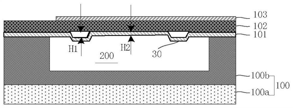
[0042] Embodiment 1 provides a thin film bulk acoustic resonator, figure 1 It is a structural schematic diagram of a thin film bulk acoustic resonator of Example 1 of the present invention, please refer to figure 1 , the film bulk acoustic resonator consists of:
[0043] A piezoelectric laminated structure, the piezoelectric laminated structure comprises a first electrode 101, a piezoelectric layer 102 and a second electrode 103 stacked sequentially from bottom to top;
[0044] At least one of the first electrode 101 and the second electrode 103 includes an annular arched bridge 30 protruding away from the surface of the piezoelectric layer 102, the inner surface of the arched bridge 30 enclosing an annular void , the area surrounded by the annular gap is the effective resonance area of the resonator.
[0045]In this embodiment, the first electrode 101 is provided with an arched bridge 30, the arched bridge 30 is a closed ring, and a gap is formed between the arched bridge...
Embodiment 2
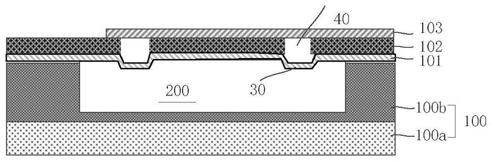
[0058] Embodiment 2 provides a thin film bulk acoustic resonator, figure 2 It is a schematic cross-sectional structure diagram of a thin-film bulk acoustic resonator in Example 2 of the present invention. The difference between this example and Example 1 is that the piezoelectric layer in Example 1 is a complete film layer, and the piezoelectric layer in Example 2 There are grooves in it, specifically:
[0059] The piezoelectric layer 102 is provided with a groove 40 running through the piezoelectric layer 102 along the boundary of the effective resonance region. In this embodiment, the groove 40 is a closed ring, and the inner sidewall of the groove 40 constitutes the boundary of the effective resonance region. The groove 40 is arranged opposite to the arch bridge 30, and the groove 40 communicates with the gap of the arch bridge. The trench 40 may not penetrate the piezoelectric layer 102 . In this embodiment, the groove 40 is a continuous ring structure. In another embod...
Embodiment 3
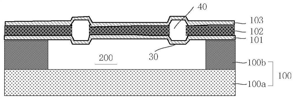
[0062] Embodiment 3 provides a thin film bulk acoustic resonator, image 3 It is a schematic cross-sectional structure diagram of a thin film bulk acoustic resonator according to Embodiment 3 of the present invention. The difference between this embodiment and Embodiment 2 is that the second electrode 103 in Embodiment 2 does not have an arched bridge structure. An arched bridge structure is also provided on the electrode 103 , and the structure of the first substrate 100 in this embodiment is different from that of Embodiment 1 and Embodiment 2.
[0063] Specifically, in this embodiment, both the second electrode 103 and the first electrode 101 are provided with an arched bridge structure, and the two arched bridges are arranged opposite to each other, and the area surrounded by the two arched bridges is the effective resonance area of the resonator. The first electrode 101 and the second electrode 103 extend from around the effective resonance region to the first substrate...
PUM
 Abstract
Description
Claims
Application Information
 - R&D Engineer
- R&D Manager
- IP Professional
- Industry Leading Data Capabilities
- Powerful AI technology
- Patent DNA Extraction
Browse by: Latest US Patents, China's latest patents, Technical Efficacy Thesaurus, Application Domain, Technology Topic.
© 2024 PatSnap. All rights reserved.Legal|Privacy policy|Modern Slavery Act Transparency Statement|Sitemap